Overview
High Availability is one of the most crucial requirements for a smooth network operation. In terms of routers or switches, we have a variety of options to choose from such as Switch-Stack, vPC, VSS, HSRP etc.
When it comes to firewalls, we only have very limited options because of the stateful nature of the firewall appliances. Most of us would usually go with an Active/Passive firewall design where the Active firewall processes the traffic and the Standby firewall just sits there and waits to take over in an event of a failure. You can also choose an Active/Active design if that suits your environment.
In this blog post, we will learn how to configure Active/Passive Failover on the Cisco ASA firewalls.
ASA Fail-Over Modes
As I mentioned before, ASA supports two failover modes, Active/Active failover and Active/Standby failover.
-
In Active/Standby failover, one device functions as the Active unit and passes the traffic. The second standby unit does not actively pass traffic. When a failover occurs, the Standby unit assumes the active role and starts passing the traffic.
-
In an Active/Active failover, both ASAs can pass traffic. Please note that Active/Active failover is only available to ASAs in multiple context modes. In Active/Active failover, you divide the security contexts on the ASA into 2 failover groups. A failover group is simply a logical group of one or more security contexts. One group is assigned to be Active on the primary ASA, and the other group is assigned to be active on the Secondary ASA. When a failover occurs, it occurs at the failover group level.
Hardware and Software Requirements
- Both units in a Failover must be the same model and have the same number and types of interfaces.
- Have the same modules installed and have the same RAM installed.
- Both units should have the same major (first number) and minor (second number) software version.
- Have the same AnyConnect images.
Failover and Stateful Failover Links
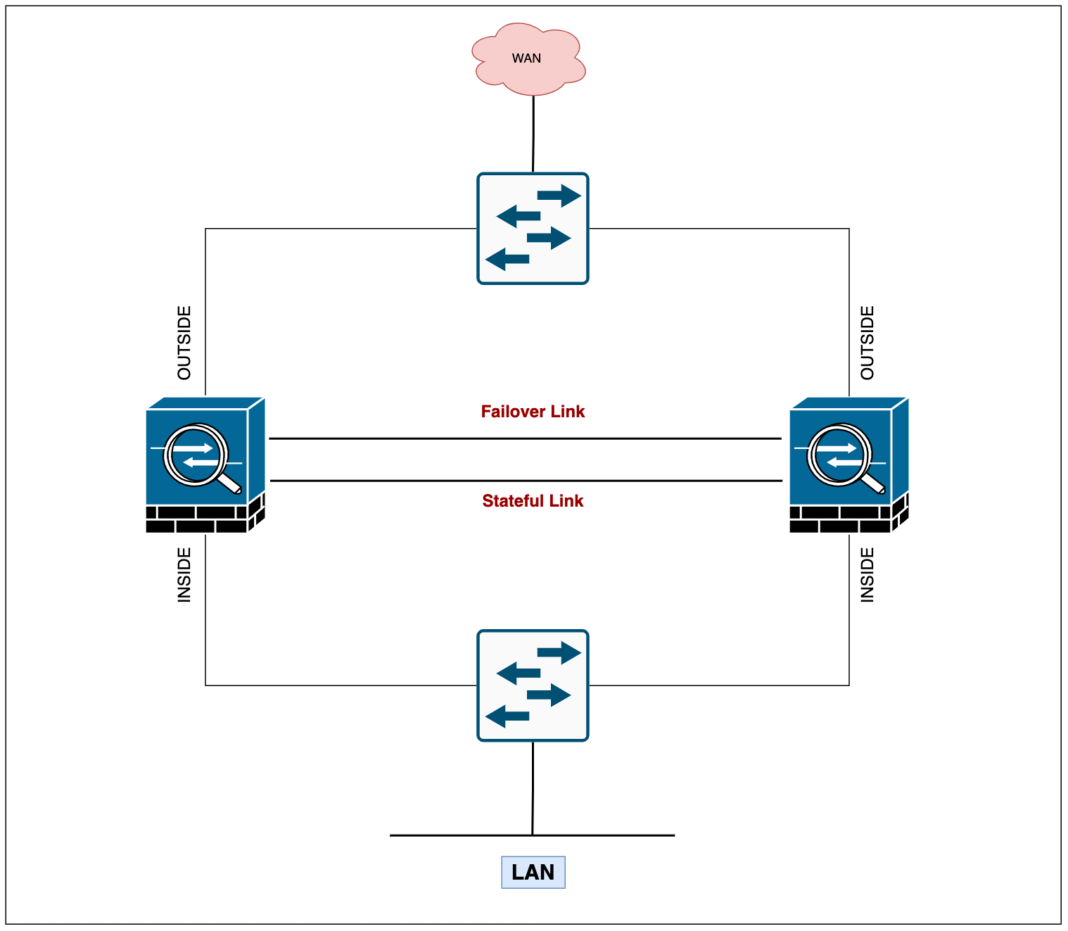
As with any other firewall cluster, you need to have some sort of connectivity between the firewalls to exchange information such as heart-beat and state information.

With the ASAs, you need two links - the failover link and the optional stateful failover link. Cisco recommends using the same interface between the two firewalls. For example, for a failover link, if you have used Gi0/1 in device 1, use the same interface Gi0/1 in device 2 as well.
- Failover Link - The two units in a failover pair constantly communicate over the failover link to determine the operating status of each unit. The failover link data includes
- The unit state (active or standby)
- Hello messages/keep-alives
- Link status
- MAC address exchange
- Configuration replication and synchronization
- Stateful Failover Link - To use Stateful Failover, you must configure a Stateful Failover link to exchange 'connection state' information. You can use a dedicated data interface (physical or Port-Channel) as the state link.
Failover Link Design
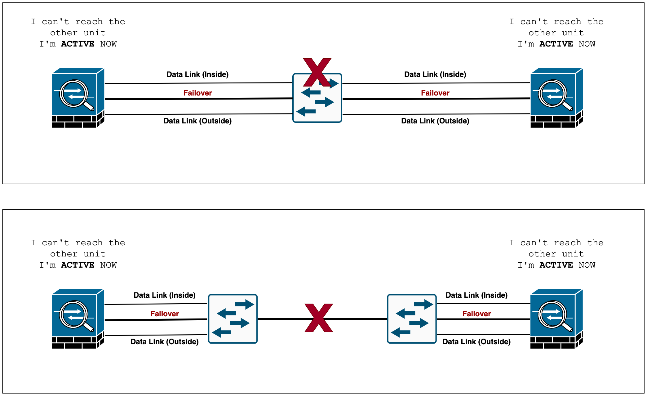
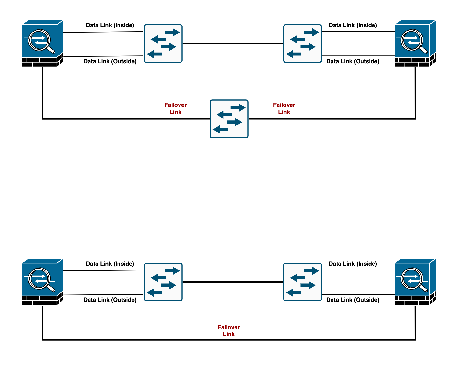
Cisco recommends that the failover links and data interfaces use different paths in order to decrease the chance of all interfaces failing at the same time. For example, If the failover link is down, the ASA can use the data interfaces to determine if a failover is necessary. Subsequently, the failover operation is suspended until the health of the failover link is restored.
Not recommended - If a single switch or a set of switches is used to connect both failover and data interfaces between two ASAs, then when a switch or inter-switch-link is down, both ASAs become active (split-brain) as shown below.

Recommended - Cisco recommends that failover links not use the same switch as the data interfaces. You can use a different switch or connect the failover link directly between the units as shown below.

MAC Addresses and IP Addresses
Standby IP Address
When you configure ASA's interfaces, you can optionally specify a standby IP address alongside the active IP address on the same subnet. When a failover occurs, the new active unit takes over the active IP addresses and MAC addresses.
! Example !

interface Gi0/1
 nameif INSIDE
 security-level 100
 ip address 10.10.12.1 255.255.255.0 standby 10.10.12.2
IP/Mac address Behaviour During Failover
The active unit always uses the primary unit's IP and MAC addresses. When a failover occurs, the standby unit assumes the IP addresses and MAC addresses of the failed unit (formerly active) and begins passing traffic.
When the failed unit comes back online, it stays in a standby state and takes over the standby IP addresses and MAC addresses.
Configuration Example
I prefer to configure the Standby IP addresses on all the interfaces even though they are optional.
interface GigabitEthernet0/0
 nameif WAN
 security-level 0
 ip address 201.85.10.1 255.255.255.248 standby 201.85.10.2
!
interface GigabitEthernet0/1
 nameif INSIDE
 security-level 100
 ip address 192.168.10.1 255.255.255.0 standby 192.168.10.2
!
Failover configuration is very straightforward. The Secondary box doesn't have any configuration except for the failover bits. The only config difference between both units is one line of config failover lan unit <primary or secondary>
failover
failover lan unit primary
failover lan interface FAILOVER-LINK GigabitEthernet0/5
failover ipsec pre-shared-key cisco123
failover link STATEFUL-LINK GigabitEthernet0/6
failover interface ip FAILOVER-LINK 192.168.100.1 255.255.255.252 standby 192.168.100.2
failover interface ip STATEFUL-LINK 192.168.100.5 255.255.255.252 standby 192.168.100.6
Primary ASA
failover
failover lan unit secondary
failover lan interface FAILOVER-LINK GigabitEthernet0/5
failover ipsec pre-shared-key cisco123
failover link STATEFUL-LINK GigabitEthernet0/6
failover interface ip FAILOVER-LINK 192.168.100.1 255.255.255.252 standby 192.168.100.2
failover interface ip STATEFUL-LINK 192.168.100.5 255.255.255.252 standby 192.168.100.6
Secondary ASA
Most of the configs are self-explanatory, I've used Gi0/5 and Gi0/6 as failover and state links respectively.
Please note that all the information sent over the failover and state links is sent in clear text. There are two ways to secure communication between peers, using IPSec PSK or a failover key, the former is recommended by Cisco.
As soon as you finish the failover configuration on both units, the console should display the following message.
asa-lab-01#
Failover LAN became OK
Switchover enabled
Configuration has changed, replicate to mate.
Beginning configuration replication: Sending to mate.
End Configuration Replication to mate
Verification
You can use show failover CLI command to check the current failover status.
asa-lab-01# show failover
Failover On
Failover unit Primary
Failover LAN Interface: FAILOVER-LINK GigabitEthernet0/5 (up)
Reconnect timeout 0:00:00
Unit Poll frequency 1 seconds, holdtime 15 seconds
Interface Poll frequency 5 seconds, holdtime 25 seconds
Interface Policy 1
Monitored Interfaces 2 of 61 maximum
MAC Address Move Notification Interval not set
Version: Ours 9.8(4), Mate 9.8(4)
Serial Number: Ours 9A077RPR8KV, Mate 9AS2E40FB75
Last Failover at: 10:01:54 UTC Oct 20 2022
        This host: Primary - Active
                Active time: 409 (sec)
                slot 0: empty
                  Interface WAN (201.85.10.1): Normal (Monitored)
                  Interface INSIDE (192.168.10.1): Normal (Monitored)
        Other host: Secondary - Standby Ready
                Active time: 6 (sec)
                  Interface WAN (201.85.10.2): Normal (Monitored)
                  Interface INSIDE (192.168.10.2): Normal (Monitored)
Primary ASA
asa-lab-01# show failover
Failover On
Failover unit Secondary
Failover LAN Interface: FAILOVER-LINK GigabitEthernet0/5 (up)
Reconnect timeout 0:00:00
Unit Poll frequency 1 seconds, holdtime 15 seconds
Interface Poll frequency 5 seconds, holdtime 25 seconds
Interface Policy 1
Monitored Interfaces 2 of 61 maximum
MAC Address Move Notification Interval not set
Version: Ours 9.8(4), Mate 9.8(4)
Serial Number: Ours 9AS2E40FB75, Mate 9A077RPR8KV
Last Failover at: 16:22:29 UTC Oct 22 2022
        This host: Secondary - Standby Ready
                Active time: 6 (sec)
                slot 0: empty
                  Interface WAN (201.85.10.2): Normal (Monitored)
                  Interface INSIDE (192.168.10.2): Normal (Monitored)
        Other host: Primary - Active
                Active time: 450 (sec)
                  Interface WAN (201.85.10.1): Normal (Monitored)
                  Interface INSIDE (192.168.10.1): Normal (Monitored)
Secondary ASA
Test Failover
Let's power-off the active unit and see what happens. Obviously, we want the secondary unit to take over the role of active and start passing the traffic.
Once we powered-off the primary ASA, we can verify the failover status from the secondary unit (now active) as shown below.
asa-lab-01# show failover history
==========================================================================
From State                 To State                   Reason
==========================================================================

10:05:12 UTC Oct 20 2022
Sync Config                Sync File System           Failover state check

10:05:12 UTC Oct 20 2022
Sync File System           Bulk Sync                  Failover state check

10:05:28 UTC Oct 20 2022
Bulk Sync                  Standby Ready              Failover state check

10:10:37 UTC Oct 20 2022
Standby Ready              Just Active                HELLO not heard from mate

10:10:37 UTC Oct 20 2022
Just Active                Active Drain               HELLO not heard from mate

10:10:37 UTC Oct 20 2022
Active Drain               Active Applying Config     HELLO not heard from mate

10:10:37 UTC Oct 20 2022
Active Applying Config     Active Config Applied      HELLO not heard from mate

10:10:37 UTC Oct 20 2022
Active Config Applied      Active                     HELLO not heard from mate

==========================================================================
asa-lab-01# show failover
Failover On
Failover unit Secondary
Failover LAN Interface: FAILOVER-LINK GigabitEthernet0/5 (up)
Reconnect timeout 0:00:00
Unit Poll frequency 1 seconds, holdtime 15 seconds
Interface Poll frequency 5 seconds, holdtime 25 seconds
Interface Policy 1
Monitored Interfaces 2 of 61 maximum
MAC Address Move Notification Interval not set
Version: Ours 9.8(4), Mate 9.8(4)
Serial Number: Ours 9AS2E40FB75, Mate 9A077RPR8KV
Last Failover at: 10:10:37 UTC Oct 20 2022
This host: Secondary - Active
Active time: 91 (sec)
slot 0: empty
Interface WAN (201.85.10.1): Normal (Waiting)
Interface INSIDE (192.168.10.1): Normal (Waiting)
Other host: Primary - Failed
Active time: 508 (sec)
Interface WAN (201.85.10.2): Unknown (Monitored)
Interface INSIDE (192.168.10.2): Unknown (Monitored)Secondary ASA (now active)
Force Failover
For whatever reason you want to force the failover, you can use the failover active command.
To force the standby unit to become active, run failover active from the standby unit or run no failover active on the active unit.
asa-lab-01# no failover active
asa-lab-01#
        Switching to Standby
active unit
Failover Interface Monitoring
By default, monitoring is enabled on all physical interfaces and on any hardware or software modules installed on the ASA, such as the ASA FirePOWER module. So, if one of the monitored links goes down on the active unit, the standby unit will take over the role.
To demonstrate interface monitoring, I'm going to shut down one of the links between the active unit and the switch.
As you can see below, the console displays a message indicating that the failover occurs due to interface monitoring. You can also use the show failover history command to check the reason behind any failover events.
asa-lab-01#
        Switching to Standby
Primary: Switching to Ok for reason Interface check.
asa-lab-01# show failover history
==========================================================================
From State To State Reason
==========================================================================
10:20:05 UTC Oct 20 2022
Active Config Applied Active Set by the config command
10:20:48 UTC Oct 20 2022
Active Failed Interface check
10:20:51 UTC Oct 20 2022
Failed Standby Ready Interface check
10:20:58 UTC Oct 20 2022
Standby Ready Failed Interface check
10:21:08 UTC Oct 20 2022
Failed Standby Ready Interface check
==========================================================================Exclude Interfaces from Monitor
If you want to exclude interfaces connected to less critical networks from affecting your failover events, you can use the no monitor-interface <interface-name> command.
asa-lab-01# show monitor-interface
        This host: Primary - Active
                Interface WAN (201.85.10.1): Normal (Monitored)
                Interface INSIDE (192.168.10.1): Normal (Monitored)
        Other host: Secondary - Standby Ready
                Interface WAN (201.85.10.2): Normal (Monitored)
                Interface INSIDE (192.168.10.2): Normal (Monitored)

asa-lab-01(config)# no monitor-interface INSIDE

asa-lab-01# show monitor-interface
        This host: Primary - Active
                Interface WAN (201.85.10.1): Normal (Monitored)
        Other host: Secondary - Standby Ready
                Interface WAN (201.85.10.2): Normal (Monitored)
As you can see above, INSIDE interface is no longer monitored for failover.
Failover EXEC mate
This is one of the commands I use frequently, suppose you are logged into the active unit but want to run some commands on the standby unit, you can use failover exec mate command followed by the actual command you want to run.
The following shows getting the show failover output from the standby unit but running the command from the active unit.
asa-lab-01# failover exec mate show failover | incl This
        This host: Secondary - Standby Ready
Failover Syslog Messages
ASA issues a number of syslog messages related to failover. The ranges of message IDs associated with failover are: 101xxx, 102xxx, 103xxx, 104xxx, 105xxx, 210xxx, 311xxx, 709xxx, 727xxx.
I've included some of the syslog messages below.
%ASA-1-104002: (Primary) Switching to STANDBY - Set by the config command
%ASA-1-104001: (Primary) Switching to ACTIVE - Set by the config command.

%ASA-1-103001: (Secondary) No response from other firewall (reason code = 4).
%ASA-1-104001: (Secondary) Switching to ACTIVE - HELLO not heard from mate.

%ASA-1-105003: (Primary) Monitoring on interface WAN waiting
%ASA-1-105003: (Primary) Monitoring on interface INSIDE waiting
%ASA-1-105004: (Primary) Monitoring on interface WAN normal
%ASA-1-105004: (Primary) Monitoring on interface INSIDE normal
%ASA-1-105003: (Primary) Monitoring on interface INSIDE waiting
%ASA-1-105004: (Primary) Monitoring on interface INSIDE normal
A few things to consider
- Even though the configuration and state information are synced across the peers, the files are not. For example, the IOS image and AnyConnect images that you require need to be uploaded into both units individually.
- Preemption is not supported in Active/Passive failover mode.
Closing up
Configuring the failover is very straightforward but understanding how it works is more crucial for troubleshooting. I've tried to cover as much as I can, however, if you would like to learn more about Failover, please check out the official Cisco guide I mentioned under the reference section.
References


