What problem does AnyCast RP solves?
Having a single active rendezvous point (RP) is a single point of failure. Anycast RP allows two or more rendezvous points (RPs) to share the load for source registration and the ability to act as hot backup routers for each other. Multicast Source Discovery Protocol (MSDP) is the key protocol that makes Anycast RP possible.
The RP routers share one unicast IP address. Sources (S,G) from one RP are known to other RPs via MSDP. Sources and receivers use the closest RP, as determined by the IGP, in our example OSPF.
Packets sent to the anycast address are sent to the nearest RP with this address.
Multicast Source Discovery Protocol
MSDP is a mechanism that allows RPs to share information about active sources.
Diagram
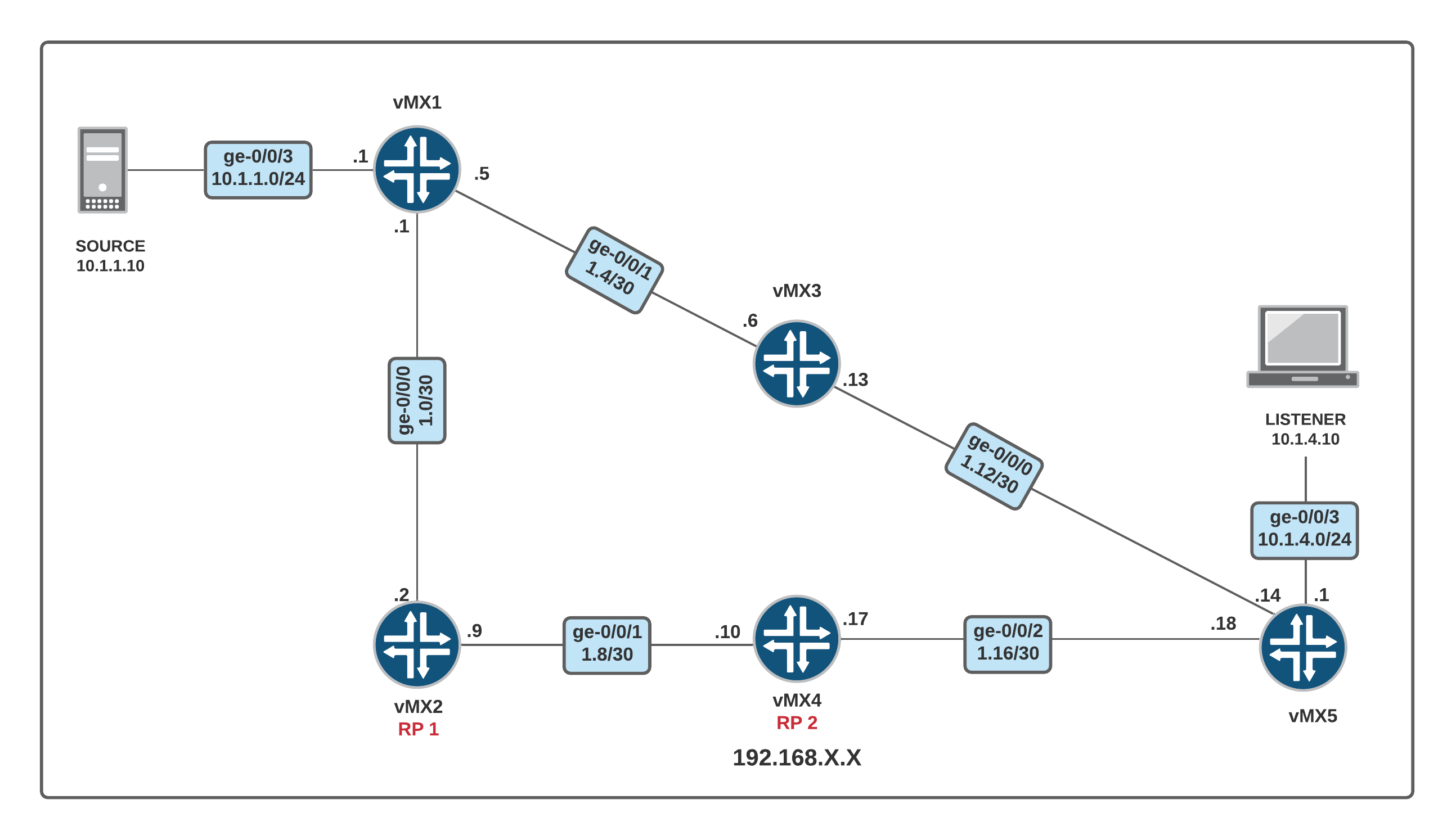
- vMX2 (RP1) is nearest to the SOURCE
- vMX4 (RP2) is nearest to the LISTENER
- RP1 and RP2 share the same (S,G) state information by using MSDP
Requirements
- Configure router interfaces
- Configure OSPF
- Configure PIM Sparse Mode on the interfaces
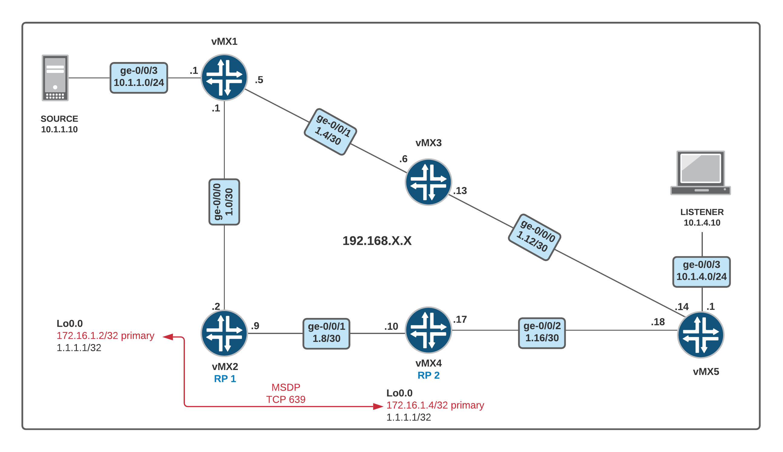
Please note that I'm configuring two IPs for Loopback 0 Interface. One as primary which is used for the router-id. The second IP is used for the RP address.
Interfaces, OSPF and PIM Sparse Mode Configuration
set system host-name vMX1
set interfaces ge-0/0/0 unit 0 family inet address 192.168.1.1/30
set interfaces ge-0/0/1 unit 0 family inet address 192.168.1.5/30
set interfaces ge-0/0/3 unit 0 family inet address 10.1.1.1/24
set protocols igmp interface ge-0/0/3.0 version 3
set protocols ospf area 0.0.0.0 interface ge-0/0/0.0
set protocols ospf area 0.0.0.0 interface ge-0/0/1.0
set protocols ospf area 0.0.0.0 interface ge-0/0/3.0
set protocols pim interface ge-0/0/0.0 mode sparse
set protocols pim interface ge-0/0/1.0 mode sparse

set system host-name vMX2
set interfaces ge-0/0/0 unit 0 family inet address 192.168.1.2/30
set interfaces ge-0/0/1 unit 0 family inet address 192.168.1.9/30
set protocols ospf area 0.0.0.0 interface ge-0/0/0.0
set protocols ospf area 0.0.0.0 interface ge-0/0/1.0
set protocols ospf area 0.0.0.0 interface lo0.0
set protocols pim interface ge-0/0/0.0 mode sparse
set protocols pim interface ge-0/0/1.0 mode sparse
set protocols pim interface lo0.0 mode sparse

set system host-name vMX3
set interfaces ge-0/0/0 unit 0 family inet address 192.168.1.13/30
set interfaces ge-0/0/1 unit 0 family inet address 192.168.1.6/30
set protocols ospf area 0.0.0.0 interface ge-0/0/0.0
set protocols ospf area 0.0.0.0 interface ge-0/0/1.0
set protocols pim interface ge-0/0/0.0 mode sparse
set protocols pim interface ge-0/0/1.0 mode sparse

set system host-name vMX4
set interfaces ge-0/0/1 unit 0 family inet address 192.168.1.10/30
set interfaces ge-0/0/2 unit 0 family inet address 192.168.1.17/30
set protocols ospf area 0.0.0.0 interface ge-0/0/1.0
set protocols ospf area 0.0.0.0 interface ge-0/0/2.0
set protocols ospf area 0.0.0.0 interface lo0.0
set protocols pim interface ge-0/0/1.0 mode sparse
set protocols pim interface ge-0/0/2.0 mode sparse
set protocols pim interface lo0.0 mode sparse

set system host-name vMX5
set interfaces ge-0/0/0 unit 0 family inet address 192.168.1.14/30
set interfaces ge-0/0/2 unit 0 family inet address 192.168.1.18/30
set interfaces ge-0/0/3 unit 0 family inet address 10.1.4.1/24
set protocols igmp interface ge-0/0/3.0 version 3
set protocols ospf area 0.0.0.0 interface ge-0/0/0.0
set protocols ospf area 0.0.0.0 interface ge-0/0/2.0
set protocols ospf area 0.0.0.0 interface ge-0/0/3.0
set protocols pim interface ge-0/0/0.0 mode sparse
set protocols pim interface ge-0/0/2.0 mode sparse
set protocols pim interface ge-0/0/3.0 mode sparse
Step 1 - Configuration of Loopback address and RP.
root@vMX1# show | compare
[edit protocols pim]
+    rp {
+        static {
+            address 1.1.1.1;
+        }
+ }root@vMX2# set protocols pim rp local address 1.1.1.1
[edit]
root@vMX2# show | compare
[edit interfaces]
+ lo0 {
+ unit 0 {
+ family inet {
+ address 172.16.1.2/32 {
+ primary;
+ }
+ address 1.1.1.1/32;
+ }
+ }
+ }
[edit protocols pim]
+ rp {
+ local {
+ address 1.1.1.1;
+ }
+ }root@vMX3# show | compare
[edit protocols pim]
+ rp {
+ static {
+ address 1.1.1.1;
+ }
+ }root@vMX4# show | compare
[edit interfaces]
+ lo0 {
+ unit 0 {
+ family inet {
+ address 172.16.1.4/32 {
+ primary;
+ }
+ address 1.1.1.1/32;
+ }
+ }
+ }
[edit protocols pim]
+ rp {
+ local {
+ address 1.1.1.1;
+ }
+ }root@vMX5# show | compare
[edit protocols pim]
+ rp {
+ static {
+ address 1.1.1.1;
+ }
+ }Let's test it. If I ssh from vMX1 to 1.1.1.1, the connection should go to vMX2.
root@vMX1> ssh root@1.1.1.1
Password:
Last login: Mon Oct 12 22:02:46 2020
--- JUNOS 18.2R1.9 Kernel 64-bit  JNPR-11.0-20180614.6c3f819_buil
root@vMX2:~ #
ssh from vMX5 should go to vMX4.
root@vMX5> ssh root@1.1.1.1
Password:
Last login: Mon Oct 12 22:37:45 2020 from 192.168.1.18
--- JUNOS 18.2R1.9 Kernel 64-bit  JNPR-11.0-20180614.6c3f819_buil
root@vMX4:~ #
Step 1 - Configuration of MSDP
Let's configure MSDP on both RPs
root@vMX2# show | compare
[edit protocols]
+   msdp {
+       local-address 172.16.1.2;
+       peer 172.16.1.4;
+   }
root@vMX4# show | compare
[edit protocols]
+   msdp {
+       local-address 172.16.1.4;
+       peer 172.16.1.2;
+   }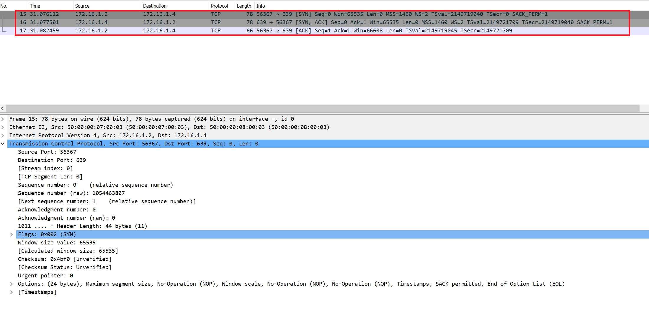
As you can see above MSDP uses TCP port 639 to establish a connection with the peer.
root@vMX2> show msdp brief
Peer address    Local address   State       Last up/down Peer-Group   SA Count
172.16.1.4      172.16.1.2      Established     00:04:36              0/0
Verification
- Let's send some traffic from the Source
SOURCE#ping 239.1.1.10 repeat 302. vMX1 (FHR) and both RPs should know about this (S,G) information, right? Let's check it out.
root@vMX1> show pim join extensive
Instance: PIM.master Family: INET
R = Rendezvous Point Tree, S = Sparse, W = Wildcard

Group: 239.1.1.10
    Source: 10.1.1.10
    Flags: sparse,spt
    Upstream interface: ge-0/0/3.0
    Upstream neighbor: Direct
    Upstream state: Local Source
    Keepalive timeout: 357
    Uptime: 00:00:03
    Downstream neighbors:
    Number of downstream interfaces: 0
Number of downstream neighbors: 0root@vMX2> show pim rps extensive
Instance: PIM.master
address-family INET
RP: 1.1.1.1
Learned via: static configuration
Mode: Sparse
Time Active: 00:44:14
Holdtime: 150
Device Index: 158
Subunit: 32769
Interface: pd-0/0/0.32769
Static RP Override: Off
Group Ranges:
224.0.0.0/4
Register State for RP:
Group Source FirstHop RP Address State Timeout
239.1.1.10 10.1.1.10 10.1.1.1 1.1.1.1 Receive 179
Anycast PIM local address used: 172.16.1.2root@vMX4> show pim join extensive
Instance: PIM.master Family: INET
R = Rendezvous Point Tree, S = Sparse, W = Wildcardroot@vMX4> show pim rps extensive
Instance: PIM.master
address-family INET
RP: 1.1.1.1
Learned via: static configuration
Mode: Sparse
Time Active: 00:23:01
Holdtime: 150
Device Index: 146
Subunit: 32769
Interface: pd-0/0/0.32769
Static RP Override: Off
Group Ranges:
224.0.0.0/4
Anycast PIM local address used: 172.16.1.4vMX4 (RP2) doesn't seem to know about the 239.1.1.10 Group yet. What are we missing here? Well, because we don't have any active listeners, MSPD is going to put this (S,G) information into the source-active cache.
root@vMX4> show msdp source-active
Global active source limit exceeded: 0
Global active source limit maximum: 25000
Global active source limit threshold: 24000
Global active source limit log-warning: 100
Global active source limit log interval: 0

Group address   Source address  Peer address    Originator      Flags
239.1.1.10      10.1.1.10       172.16.1.2      172.16.1.2      Accept
If RP1 goes down, the current multicast flow won't be affected becasue the traffic is flowing via the SPT. RP is only hosting the control plane information, the data plane traffic doesn't necessarliy go via the RP. If a new Source starts sending multicast traffic, the PIM Register message goes to the RP2.
Reference
Thanks for reading.
As always, your feedback and comments are more than welcome.