PIM Sparse mode uses an 'explicit join' approach whereas PIM Dense mode uses 'implicit join' approach. With PIM Sparse mode, only network segments with active receivers that have explicitly requested the data will receive the traffic.
PIM sparse mode distributes information about active sources by forwarding data packets on the shared tree. In a shared tree, the root of the distribution tree is a router which is located somewhere in the core of the network. In PIM Sparse Mode, the core router at the root of the shared tree is the rendezvous point (RP). Packets from the upstream source and join messages from the downstream routers “rendezvous” at this core router.
In the RP model, other routers do not need to know the addresses of the sources for every multicast group. All they need to know is the IP address of the RP router. The RP router discovers the sources for all multicast groups.
We can statically configure RP on each routers or use some protocols which can discover RP in the network.
The (*,G) or (S,G) entries is the information used for forwarding unicast or multicast packets. S is the source IP address, G is the multicast group address, and * represents any source sending to group G. Routers keep track of the multicast forwarding state for the incoming and outgoing interfaces for each group.
- First-Hop Router (FHR) where the senders (source) connect
- Last-Hop Router (LHR) where the receivers connect
DR election
A designated router (DR) sends periodic join messages and prune messages toward a group-specific rendezvous point (RP) for each group for which it has active members.
By default, every PIM interface has an equal probability (priority 1) of being selected as the DR, but you can change the value to increase or decrease the chances of a given DR being elected. A higher value corresponds to a higher priority, that is, greater chance of being elected.
In our example, vMX4 is configured with higher DR priority.
root@vMX4# show | compare
[edit protocols pim interface ge-0/0/0.0]
+    priority 5;
[edit protocols pim interface ge-0/0/2.0]
+    priority 5;
Tunnel Services PICs and Multicast
On Juniper MX Series routers, data packets are encapsulated and de-encapsulated into tunnels by means of hardware and not the software running on the router processor.
The hardware used to create tunnel interfaces on MX Series routers is a Tunnel Services PIC. So, a Tunnel Services PIC is required on both RP router and the First Hop Router connected to the source.
You must enable tunnel services with the tunnel-services statement on one or more online FPC and PIC combinations at the edit chassis fpc number pic number hierarchy level.
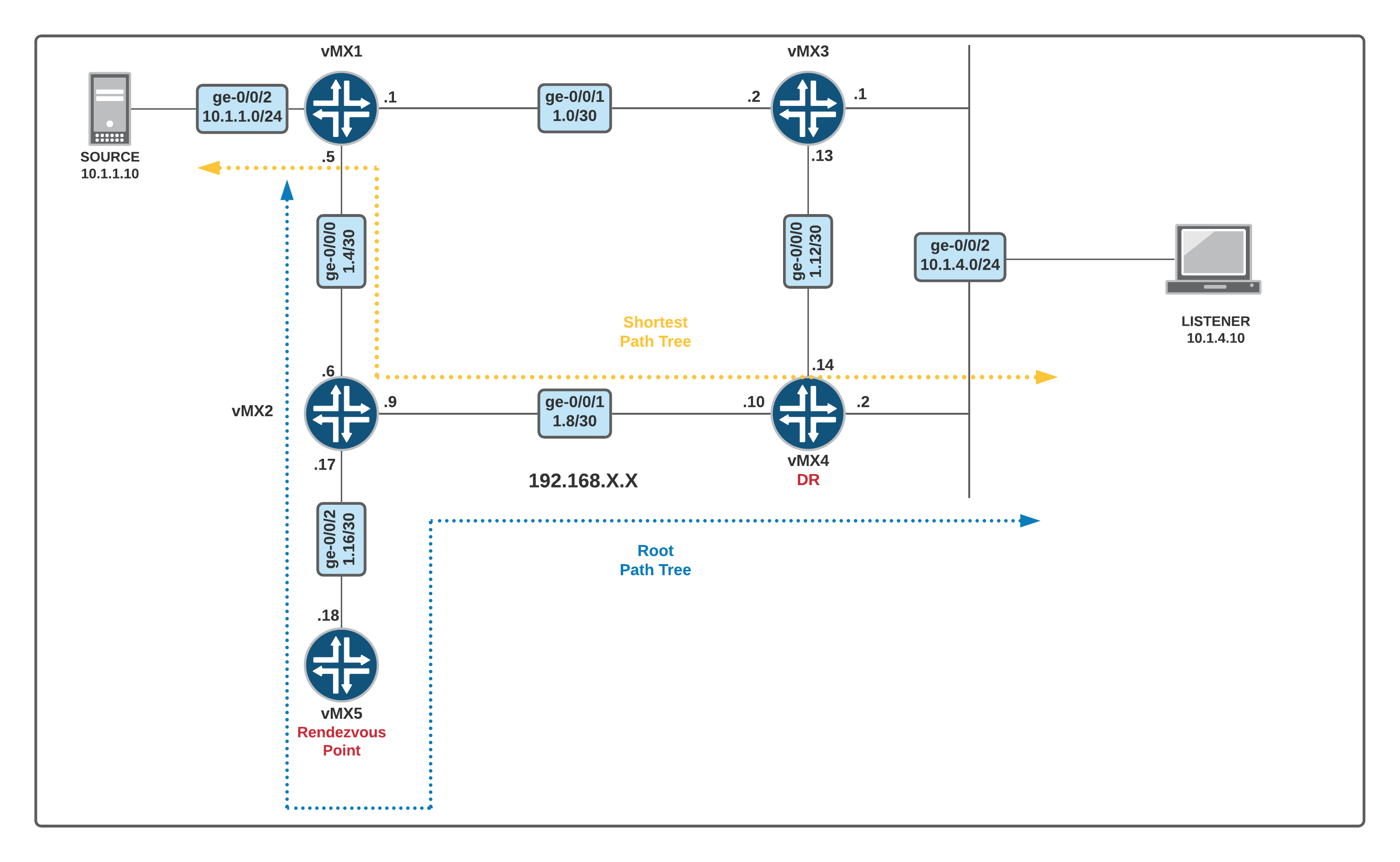
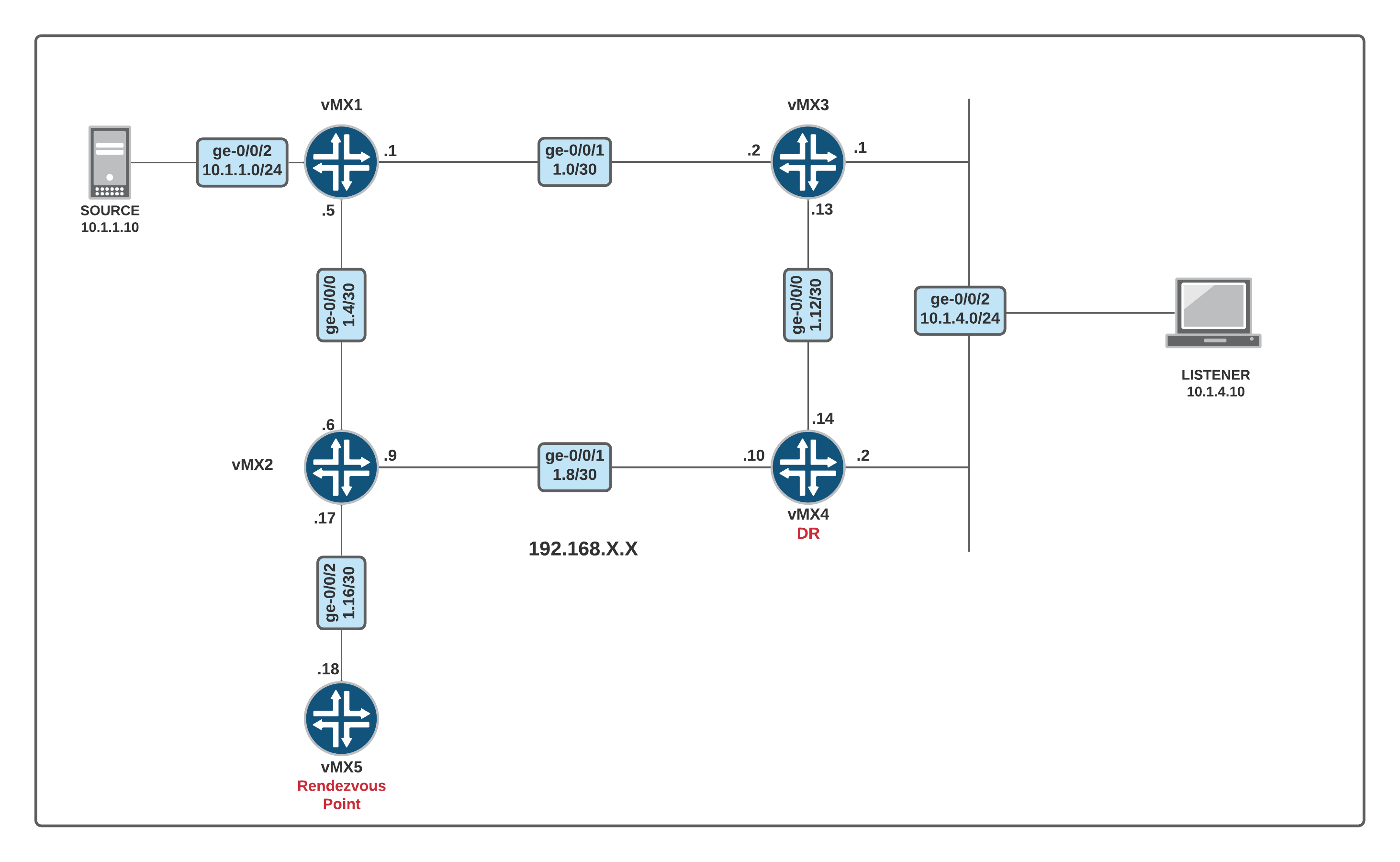
Diagram
Configuration
vMX1
set system host-name vMX1
set chassis fpc 0 pic 0 tunnel-services
set interfaces ge-0/0/0 unit 0 family inet address 192.168.1.5/30
set interfaces ge-0/0/1 unit 0 family inet address 192.168.1.1/30
set interfaces ge-0/0/2 unit 0 family inet address 10.1.1.1/24
set protocols ospf area 0.0.0.0 interface ge-0/0/0.0
set protocols ospf area 0.0.0.0 interface ge-0/0/1.0
set protocols ospf area 0.0.0.0 interface ge-0/0/2.0
set protocols pim rp static address 5.5.5.5
set protocols pim interface ge-0/0/0.0 mode sparse
set protocols pim interface ge-0/0/1.0 mode sparse
set protocols pim interface ge-0/0/2.0 mode sparse

vMX2
set system host-name vMX2
set interfaces ge-0/0/0 unit 0 family inet address 192.168.1.6/30
set interfaces ge-0/0/1 unit 0 family inet address 192.168.1.9/30
set interfaces ge-0/0/2 unit 0 family inet address 192.168.1.17/30
set protocols ospf area 0.0.0.0 interface ge-0/0/0.0
set protocols ospf area 0.0.0.0 interface ge-0/0/1.0
set protocols ospf area 0.0.0.0 interface ge-0/0/2.0
set protocols pim rp static address 5.5.5.5
set protocols pim interface ge-0/0/0.0 mode sparse
set protocols pim interface ge-0/0/1.0 mode sparse
set protocols pim interface ge-0/0/2.0 mode sparse

vMX3
set system host-name vMX3
set interfaces ge-0/0/0 unit 0 family inet address 192.168.1.13/30
set interfaces ge-0/0/1 unit 0 family inet address 192.168.1.2/30
set interfaces ge-0/0/2 unit 0 family inet address 10.1.4.1/24
set protocols ospf area 0.0.0.0 interface ge-0/0/0.0
set protocols ospf area 0.0.0.0 interface ge-0/0/1.0
set protocols ospf area 0.0.0.0 interface ge-0/0/2.0
set protocols pim rp static address 5.5.5.5
set protocols pim interface ge-0/0/0.0 mode sparse
set protocols pim interface ge-0/0/1.0 mode sparse
set protocols pim interface ge-0/0/2.0 mode sparse

vMX4
set system host-name vMX4
set interfaces ge-0/0/0 unit 0 family inet address 192.168.1.14/30
set interfaces ge-0/0/1 unit 0 family inet address 192.168.1.10/30
set interfaces ge-0/0/2 unit 0 family inet address 10.1.4.2/24
set protocols ospf area 0.0.0.0 interface ge-0/0/0.0
set protocols ospf area 0.0.0.0 interface ge-0/0/1.0
set protocols ospf area 0.0.0.0 interface ge-0/0/2.0
set protocols pim rp static address 5.5.5.5
set protocols pim interface ge-0/0/0.0 mode sparse
set protocols pim interface ge-0/0/1.0 mode sparse
set protocols pim interface ge-0/0/2.0 mode sparse
set protocols pim interface ge-0/0/0.0 priority 5
set protocols pim interface ge-0/0/2.0 priority 5

vMX5
set system host-name vMX5
set chassis fpc 0 pic 0 tunnel-services
set interfaces ge-0/0/2 unit 0 family inet address 192.168.1.18/30
set interfaces lo0 unit 0 family inet address 5.5.5.5/32
set protocols ospf area 0.0.0.0 interface ge-0/0/2.0
set protocols ospf area 0.0.0.0 interface lo0.0
set protocols pim rp local address 5.5.5.5
set protocols pim interface lo0.0 mode sparse
set protocols pim interface ge-0/0/2.0 mode sparse
Scenario 1 - Active Source but no Listeners
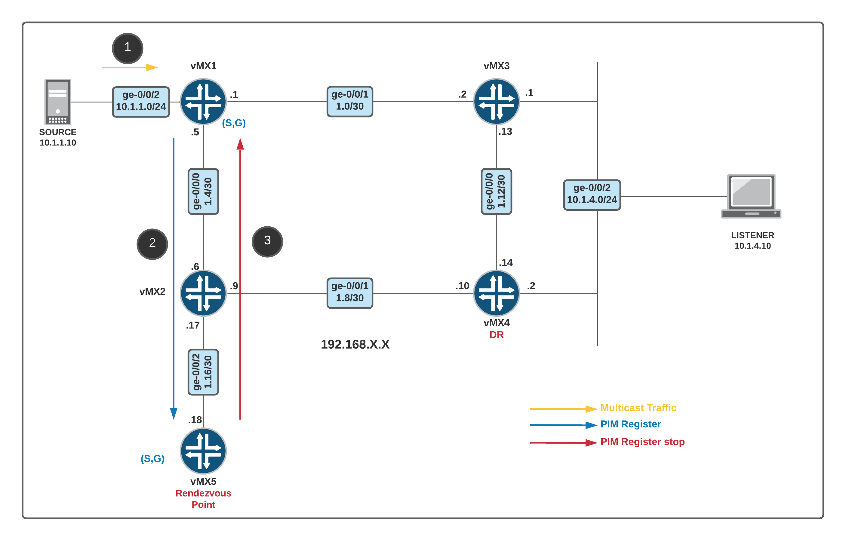
When the source start sending multicast traffic, the FHR/DR Router encapsulates the traffic inside unicast PIM Register Message and send it to the RP. In our case, FHR is vMX1 and the RP is vMX5.
Please note that if you have multiple FHRs in the LAN segment only DR sends the PIM register message towards the RP.
Let's send some multicast traffic from the source to 239.1.1.1 and see what happens.
Please note that we don't have any listeners at the moment.
SOURCE

no ip routing
ip default-gateway 10.1.1.1

interface GigabitEthernet0/0
 ip address 10.1.1.10 255.255.255.0

SOURCE#ping 239.1.1.1- vMX1 aka FHR encapsulates multicast data packets into a PIM register message and sends them by means of unicast to the RP router.
- The RP router (vMX5) receives PIM register messages back from the source, and thus adds a new source to the distribution tree, keeping track of sources in a PIM table.
- If there are no listeners then the RP will send PIM register-Stop message. The DR Router/FHR will not send any more PIM Register messages for a fixed timeout.
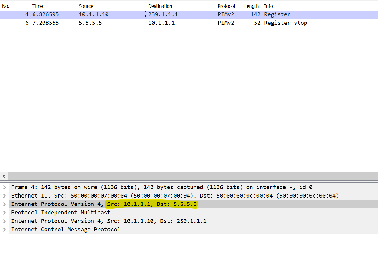
We can verify both 'register' and 'register stop' messages using packet capture.
Wireshark is showing the first packet as a multicast packet (Source - 10.1.1.10, Destination - 239.1.1.1) but actually it is an Unicast packet which has a multicast packet encapsulated. So, please refer to to the highlighted IP header rather than the one showing on top.
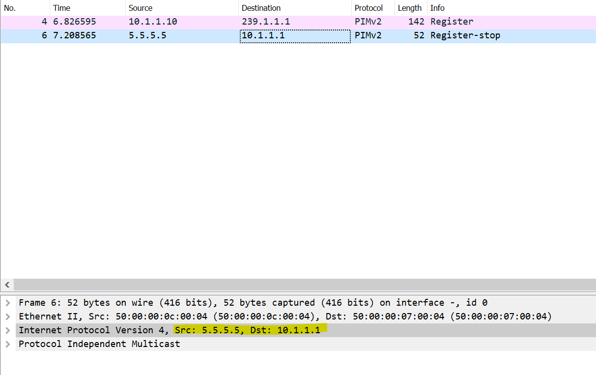
PIM Register Stop - RP is telling the FHR that there are no listeners so, don't send any more multicast packets if you have them. This is again an unicast message.
Verification on FHR and RP
You can use show pim join extensive command on the FHR to check the (S,G) information. root@vMX1> show pim join extensive
Instance: PIM.master Family: INET
R = Rendezvous Point Tree, S = Sparse, W = Wildcard
Group: 239.1.1.1
Source: 10.1.1.10
Flags: sparse,spt
Upstream interface: ge-0/0/2.0
Upstream neighbor: Direct
Upstream state: Local Source
Keepalive timeout: 312
Uptime: 00:00:48
Downstream neighbors:
Number of downstream interfaces: 0
Number of downstream neighbors: 0- vMX1 creates (S,G) information about an active source.
Group: 239.1.1.1andSource: 10.1.1.10 Upstream interface: ge-0/0/2- This is where our source is connected.Upstream neighbor: Direct- Direct means, vMX1 is not receiving a multicast packet from a PIM neighbor rather receiving directly from the source.Upstream state: Local Source- The source is directly connected
You can use show pim rps extensive command on the RP to check the PIM register state. root@vMX5> show pim rps extensive
Instance: PIM.master
address-family INET
RP: 5.5.5.5
Learned via: static configuration
Mode: Sparse
Time Active: 00:01:55
Holdtime: 150
Device Index: 146
Subunit: 32769
Interface: pd-0/0/0.32769
Static RP Override: Off
Group Ranges:
224.0.0.0/4
Register State for RP:
Group Source FirstHop RP Address State Timeout
239.1.1.1 10.1.1.10 10.1.1.1 5.5.5.5 Receive 183- vMX5 which is the RP also creates (S,G) information about the active soure.
GroupandSourceare self explanatoryFirstHop- Junos is using the interface facing the source as the FirstHop IP. I believe Cisco uses the exit interface.RP Address- Self explanatoryState- RP received the PIM register message
Scenario 2 - Active listeners but no Source
When a receiver issues an explicit join request:
- An RPF check is triggered.
- A (*,G) PIM join message is sent toward the RP from the receiver's designated router (DR).
- The join message is multicast hop by hop upstream to the all PIM routers group (224.0.0.13) .
- The RP router receives the (*,G) PIM join message and adds the interface on which it was received to the outgoing interface list (OIL) of the rendezvous-point tree (RPT) forwarding state entry.
- This builds the RPT connecting the receiver with the RP. The RPT remains in effect, even if no active sources generate traffic.
Let's configure a listener. I'm using a cisco router as a listener.
I have also stopped the source from sending multicast traffic. So, at this point we only have a listener but there is no source.
LISTENER

no ip routing
ip default-gateway 10.1.4.1

interface GigabitEthernet0/0
 ip address 10.1.4.10 255.255.255.0
 ip igmp join-group 239.1.1.1
root@vMX5> show pim join extensive
Instance: PIM.master Family: INET
R = Rendezvous Point Tree, S = Sparse, W = Wildcard

Group: 239.1.1.1
    Source: *
    RP: 5.5.5.5
    Flags: sparse,rptree,wildcard
    Upstream interface: Local
    Upstream neighbor: Local
    Upstream state: Local RP
    Uptime: 00:02:32
    Downstream neighbors:
        Interface: ge-0/0/2.0
            192.168.1.17 State: Join Flags: SRW Timeout: 178
            Uptime: 00:02:32 Time since last Join: 00:00:32
    Number of downstream interfaces: 1
    Number of downstream neighbors: 1

Instance: PIM.master Family: INET6
R = Rendezvous Point Tree, S = Sparse, W = Wildcard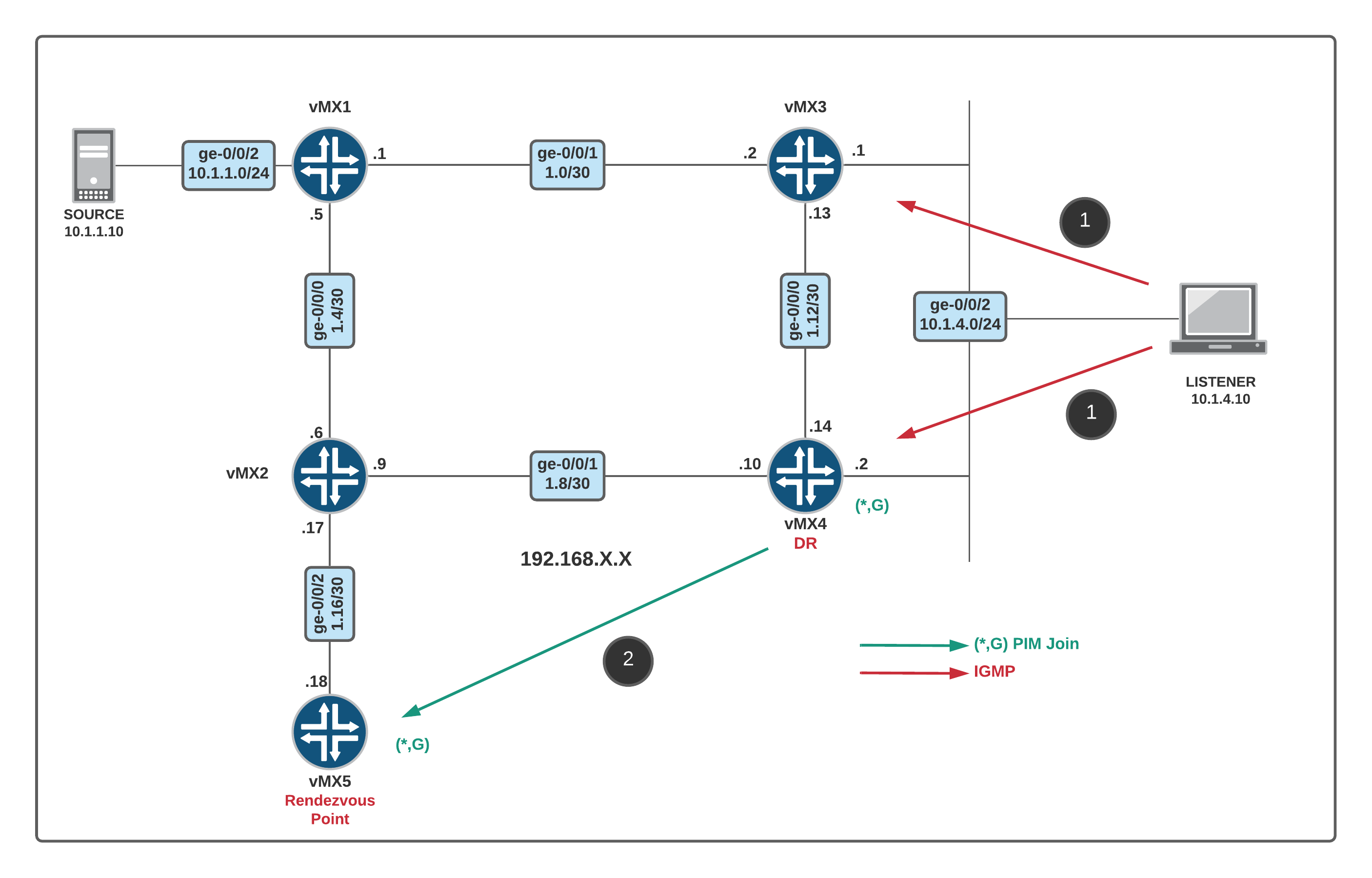
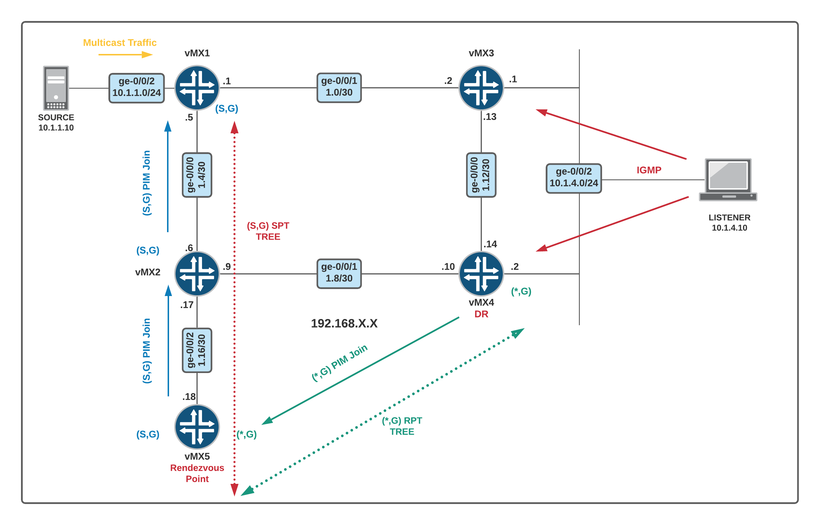
Scenario 3 - Source + Active Listener
When the RP has active listeners (*,G) and receives the first PIM Register message:
- RP de-capsulates the multicast packet from the register message and send it down the (*,G) tree (towards the listener)
- RP sends (S,G) Join message towards the source hop-by-hop (vMX5 > vMX2 > vMX1) Basically it asks the FHR to send the RAW multicast packets.
- Once the RP starts receiving the multicast packets natively over the (S,G) tree, it sends a Register-Stop message.
- Finally, the multicast traffic is flowing from the source to the Listener via (S,G) and (*,G) trees.
- (S,G) Tree (SPT) - vMX1 > vMX2 > vMX5
- (*,G) Tree (RPT) - vMX5 > vMX2 > vMX4
SPT Switchover
One of the reason for the SPT switchover is that traffic flow via the RP may not be the most optimal path.
RP router begins sending multicast packets down the RPT toward the receiver’s DR for delivery to the interested receivers. When the receiver’s DR (LHR) receives the first packet from the RPT, the DR sends a PIM join message toward the source DR to start building an SPT back to the source.
When the source DR receives the PIM join message from the receiver’s DR, it starts sending traffic down all SPTs. When the first multicast packet is received by the receiver’s DR, the receiver’s DR sends a PIM prune message to the RP router to stop duplicate packets from being sent through the RPT.
In turn, the RP router stops sending multicast packets to the receiver’s DR, and sends a PIM prune message for this source over the RPT toward the source DR to halt multicast packet delivery to the RP router from that particular source. The actual Data Plane traffic starts flowing via the Shortest Path Tree from the source to receiver.
The RP only hosts the control plane information and the traffic doesn't necessarily need to flow via the RP.
After the SPT switchover the multicast traffic flows from the Source to the Listener via Source >vMX1 > vMX2 > vMX4 > Listener