In this blog post, we'll look at how to create a site-to-site VPN between AWS and a Palo Alto firewall. We'll go through both static routing and BGP options. This post assumes you're already somewhat familiar with AWS and Palo Alto, so we won't cover the basics like creating a VPC in AWS or setting up zones and policies on the firewall.
Overview
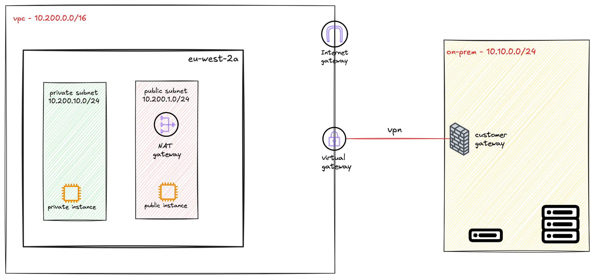
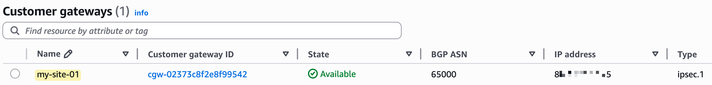
To create a VPN connection, you first need a compatible IPsec VPN device, like a firewall or router, at your on-premise location. In AWS, the resource you create to represent this device is called a Customer Gateway. In our example, the customer gateway is the Palo Alto firewall.
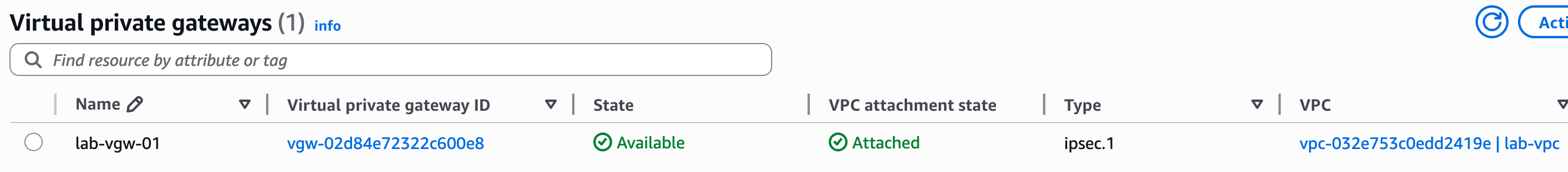
To send traffic from your VPC to your on-premise network, you route it to a Virtual Private Gateway (VGW). The VGW is a logical, redundant resource on the AWS side of the connection that you attach to your VPC. It serves as the target in your route tables for any traffic destined for your on-premise network.
AWS Provides Two Tunnels
When you create a single VPN connection, AWS automatically provisions two distinct VPN tunnels for you. This is done to ensure high availability for the connection between your on-premise network and your VPC.
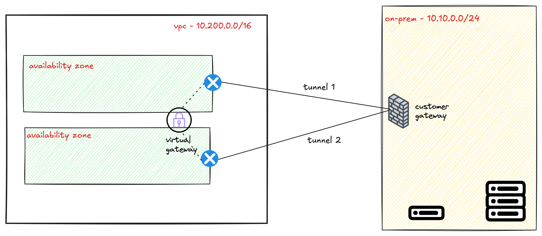
Each of these two tunnels terminates on a separate, redundant endpoint within the AWS network. These endpoints are located in different Availability Zones to protect against an issue affecting a single data centre. Your on-premise device should be configured to connect to both of these tunnel endpoints to take full advantage of this fault-tolerant design.
Static Routing vs BGP
When setting up a Site-to-Site VPN, you can choose between static or BGP routing. With static routing, you need to manually add routes pointing to the VPN tunnel interface. The device won’t know if the tunnel is down unless you use a feature like tunnel monitoring. In Palo Alto, you can combine this with policy-based forwarding and a monitor profile to fail over to the second tunnel.
With BGP, there's no need to configure static routes. Routing information is exchanged dynamically, and BGP handles failover.
Creating the VPN Connection (Static)
Let's assume you've already created the Customer Gateway, the Virtual Private Gateway (VGW), and attached the VGW to your VPC. The next step is to create the actual VPN connection.
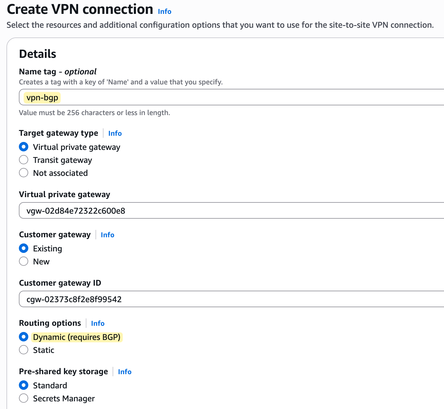
To begin creating the VPN, navigate to the 'Site-to-Site VPN connections' section within the VPC console and click 'Create VPN connection'. This will open a configuration wizard. You'll give the connection a descriptive name, like lab-vpn, and then select the Virtual Private Gateway (VGW) and the Customer Gateway (CGW) that we created in the previous steps.
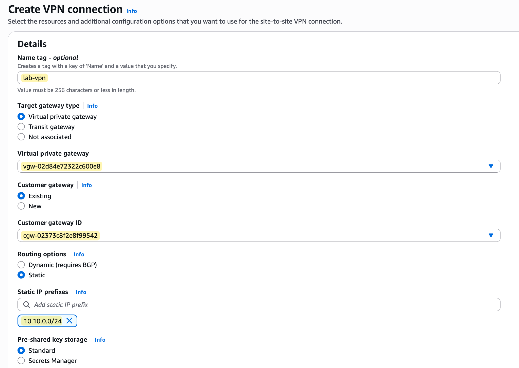
For this example, we will select 'Static' for the routing options and manually enter the IP prefixes for our on-premise network, which we want the VPC to be able to communicate with. In our case, the prefix that belongs to the on-prem network is 10.10.0.0/24
Further down the page, you can configure the specific options for each of the two tunnels. A key requirement for the VPN to work is that each tunnel has its own internal IP addresses for routing.
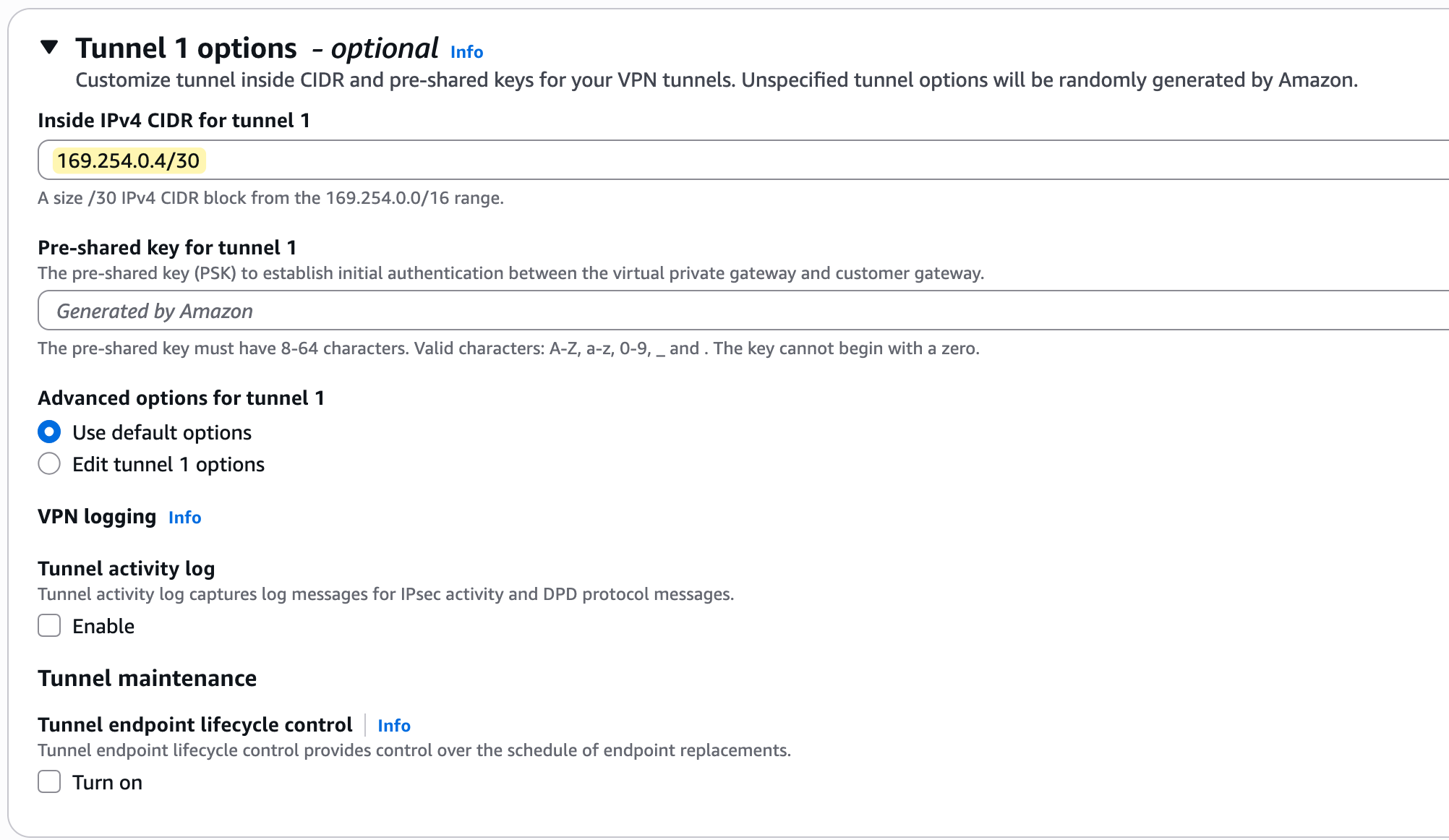
These IPs must come from the 169.254.0.0/16 address range, with each tunnel needing a /30 CIDR block for its point-to-point connection. You can either enter these manually or leave them blank for AWS to generate them for you.
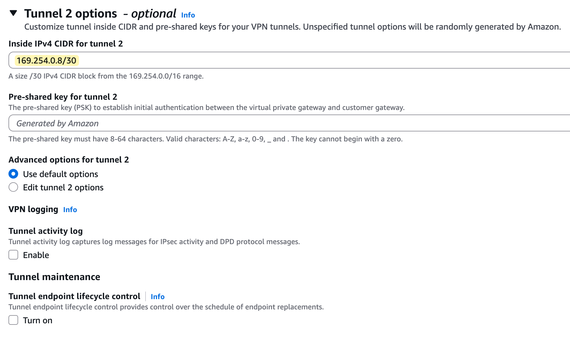
You will also see that AWS generates a unique Pre-Shared Key (PSK) for each tunnel, which is used for authentication.
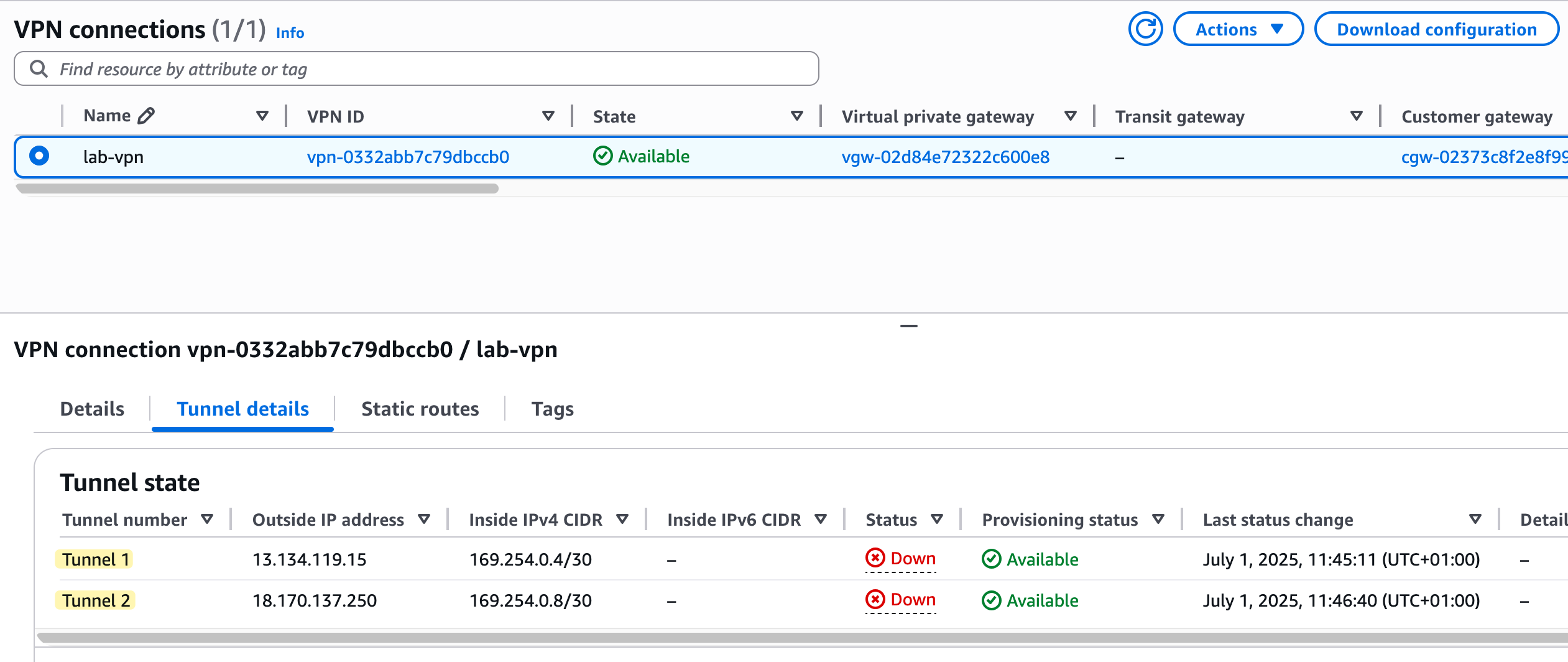
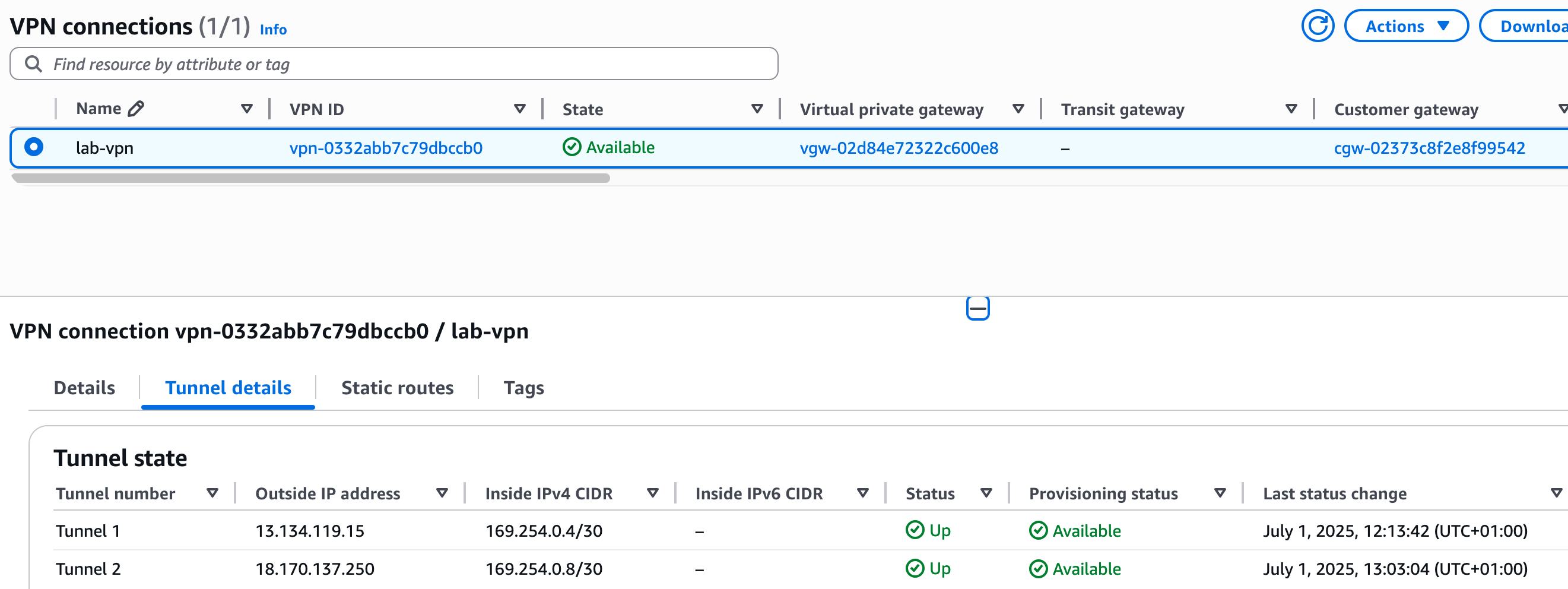
After you create the connection, the state will change to 'Available', but if you look at the 'Tunnel details' tab, you will notice the status for both tunnels is 'Down'. This is normal and expected because we have only configured the AWS side of the connection.
Palo Alto Side Configuration (Static)
On the AWS side, we went with mostly default values and didn’t manually pick specific encryption or authentication algorithms. So on the Palo Alto side, we can use the default profiles that come with the firewall.
Crypto Profiles
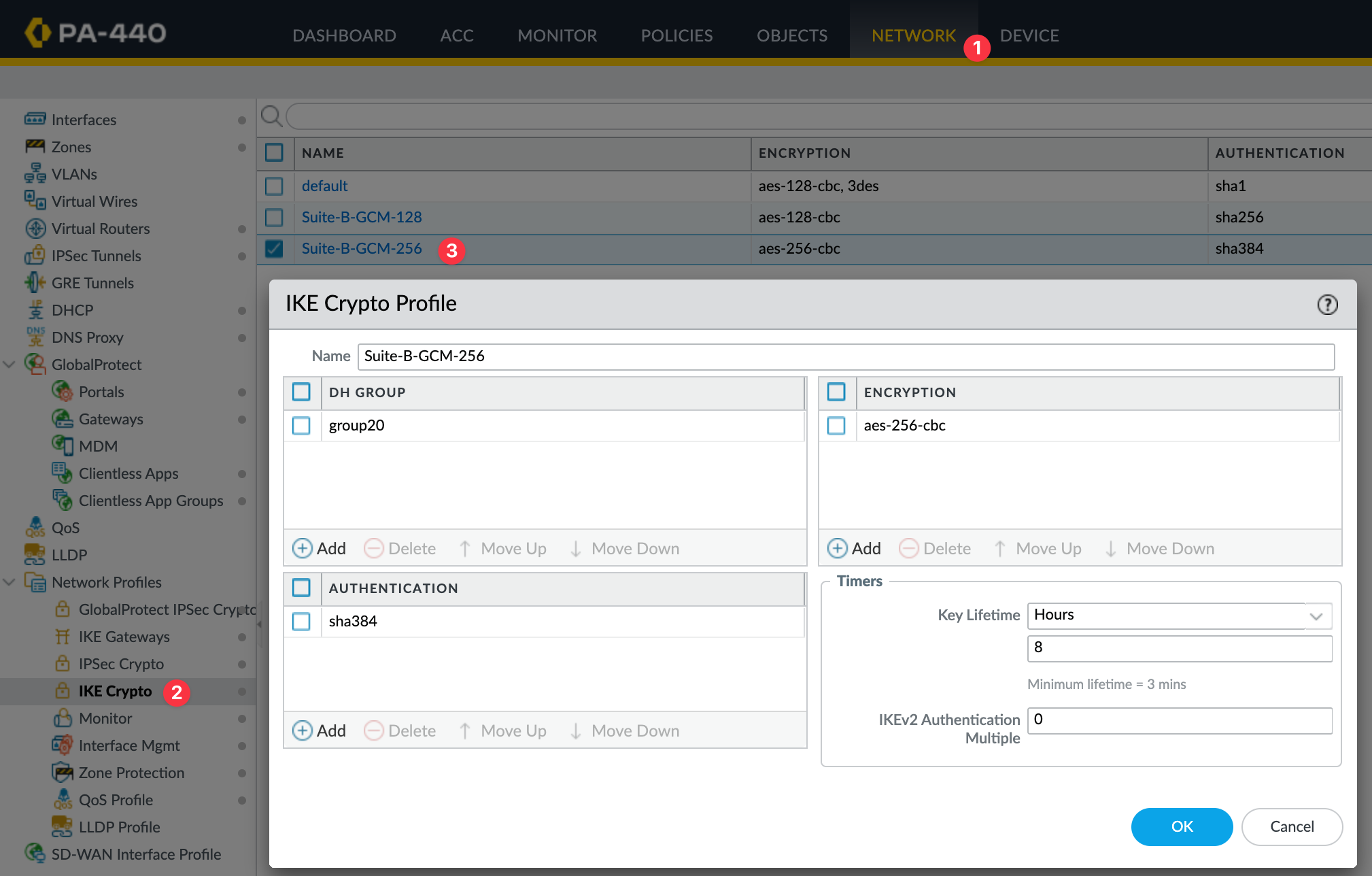
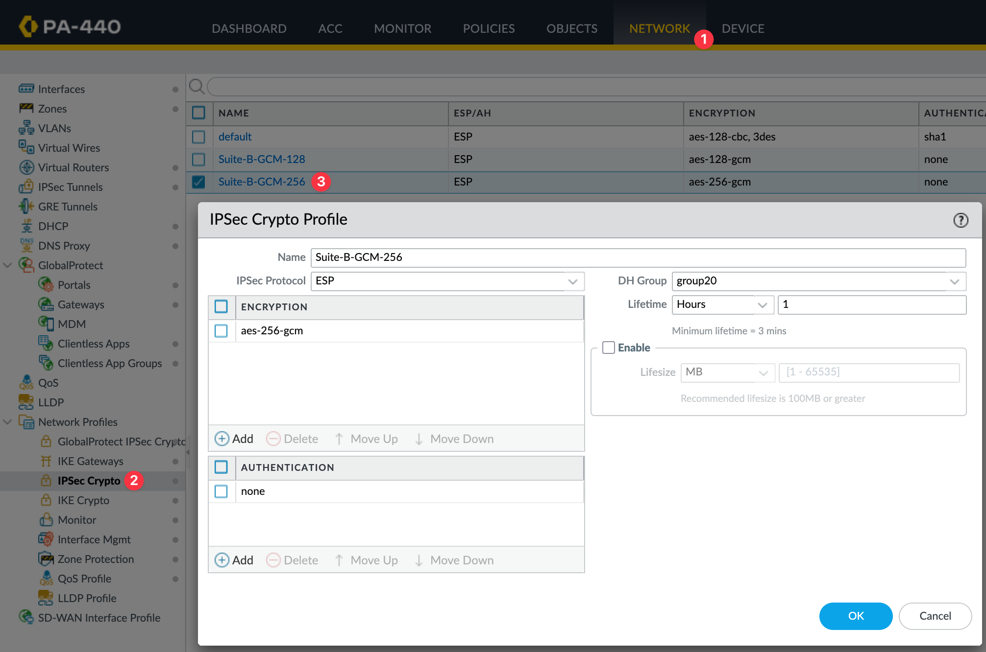
I'm going to use the IKE Crypto Profile Suite-B-GCM-256 and the IPsec Crypto Profile Suite-B-GCM-256, both of which are available by default.
Zones and Tunnel Interfaces
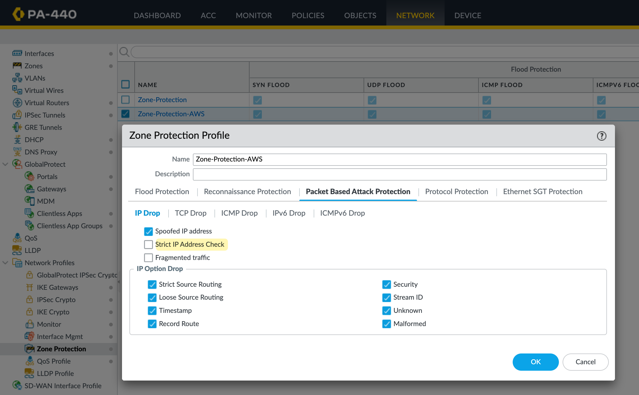
I'm going to create a new zone for the tunnel and call it AWS-IPSEC. The key thing here is the Zone Protection Profile. Either set it to None or make sure the profile you apply has 'Strict IP Address Check' disabled.
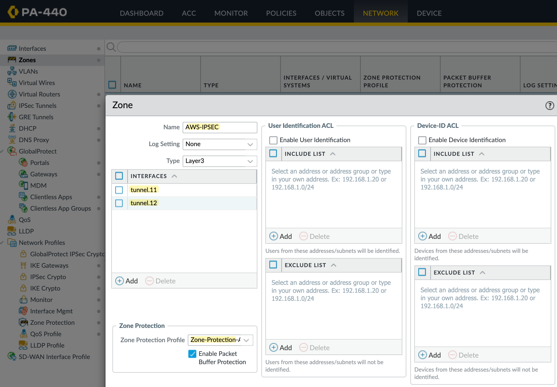
Without this, you'll run into issues with policy-based forwarding because the tunnel IPs fall under the 169.254.0.0/16 range, which is link-local. The firewall will drop traffic to these IPs, and your PBF rules won’t work as expected.
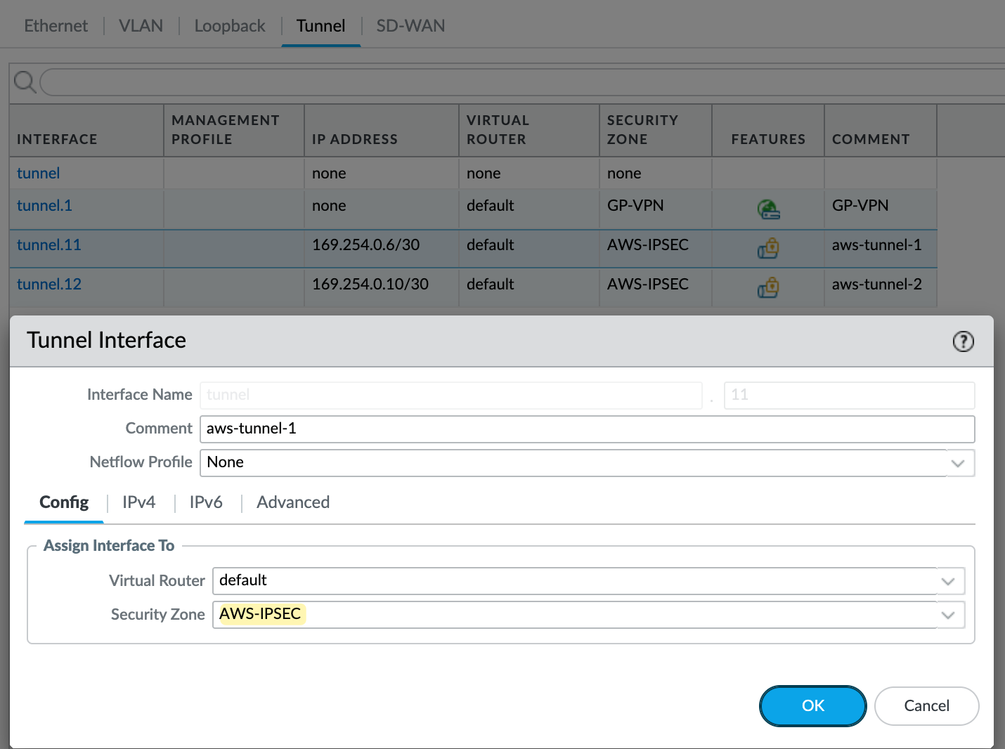
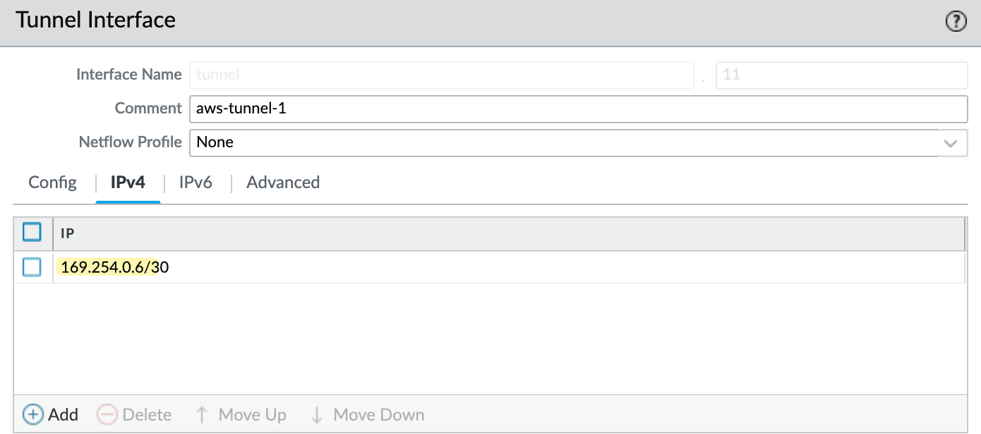
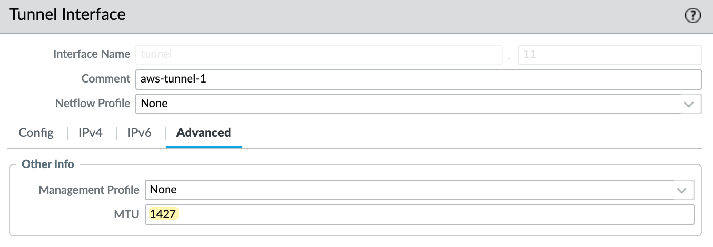
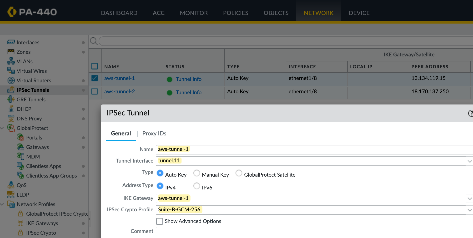
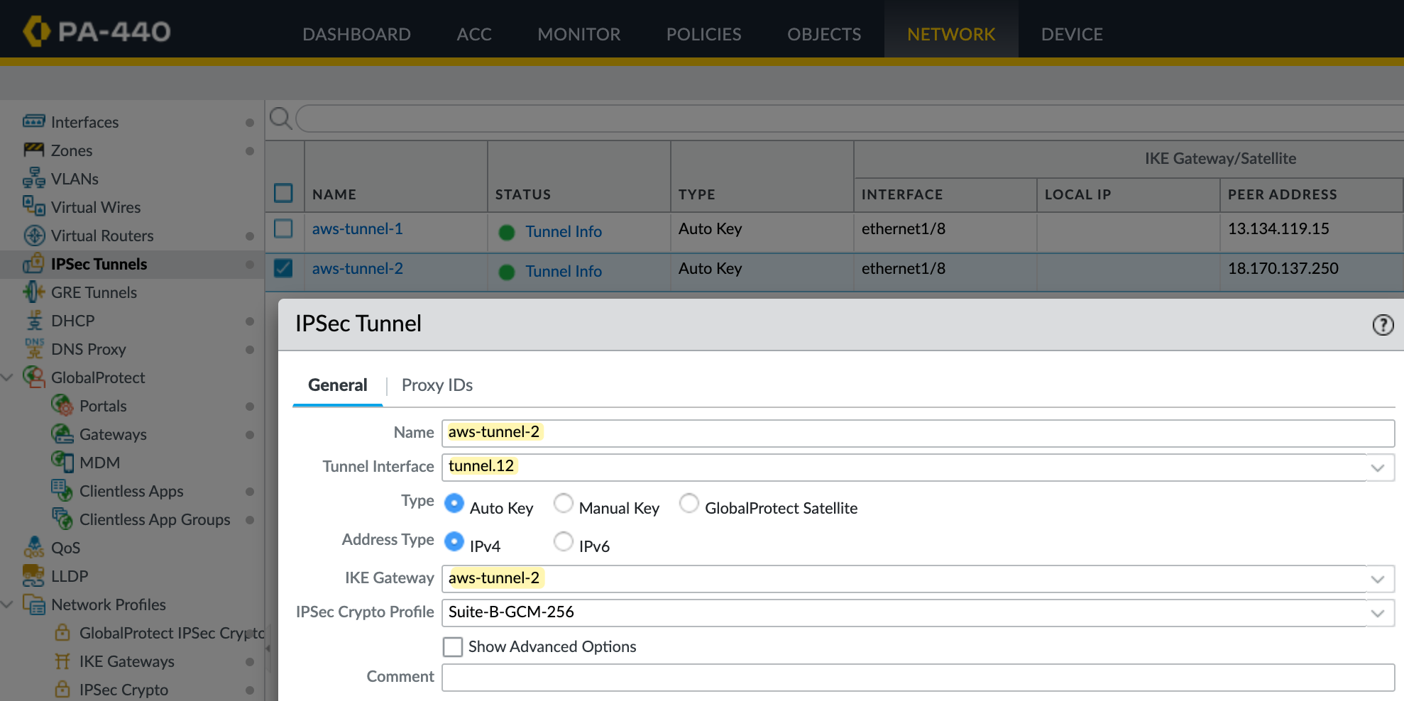
Next, I’ll create two tunnel interfaces - tunnel.11 and tunnel.12. Each will be assigned an IP address from the /30 range defined in the AWS VPN config. The higher IP in the /30 is for our tunnel, and the lower is used by AWS. So, for example, I’ll use 169.254.0.6/30 and 169.254.0.10/30. Make sure to set the MTU to 1427 and assign these interfaces to the AWS-IPSEC zone. You can see the config for one of the tunnels in the attached screenshot.
IKE Gateway
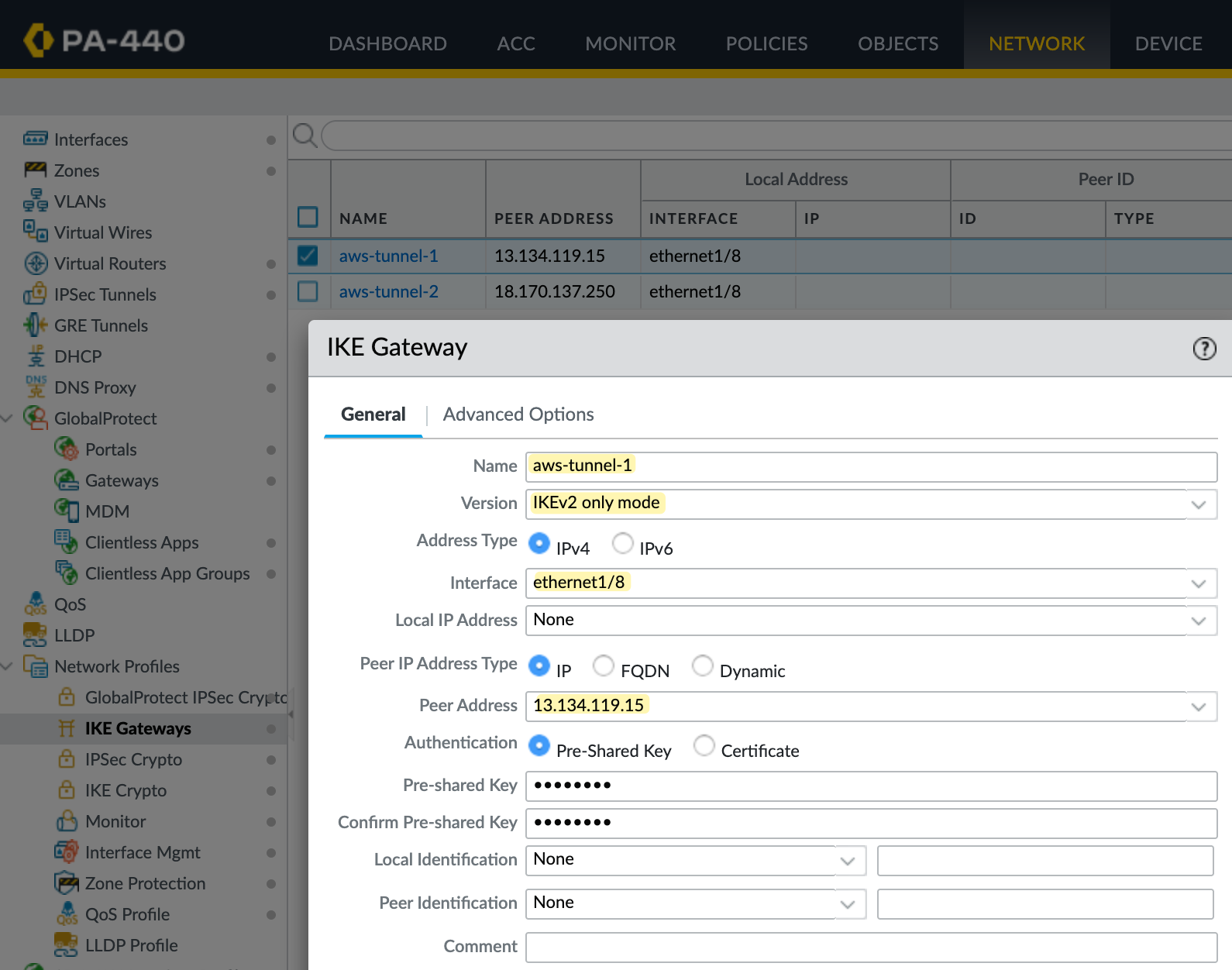
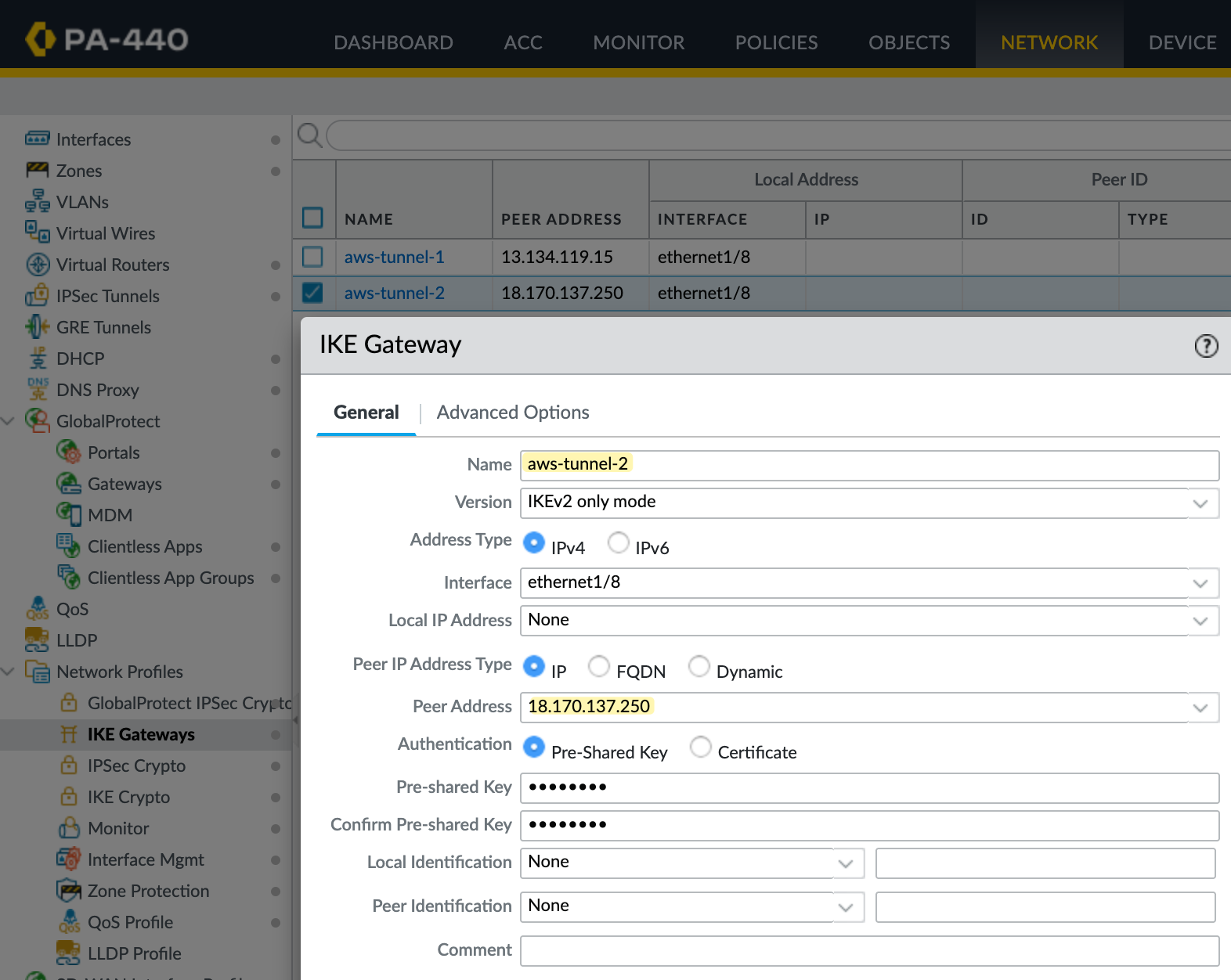
Next, let’s create the IKE Gateway. You’ll need to create two of them, one for each tunnel. Here, you specify your external interface and IP address, which is ethernet1/8 in my case. You also need to set the peer IP, which comes from AWS, and the pre-shared key (PSK), which you can also get from the AWS VPN config.
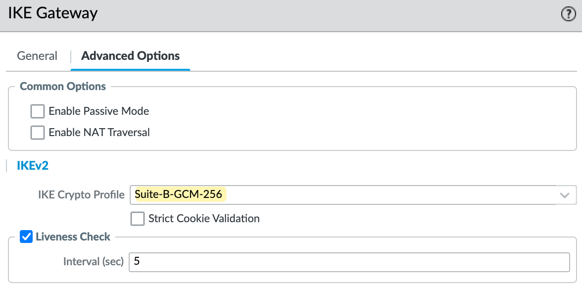
I'm using IKEv2 for this setup. Under the advanced options, make sure you select the correct IKE crypto profile. In my case, I’m using Suite-B-GCM-256, as shown in the screenshot.
IPSec Tunnel
Next, create the IPSec tunnel and bring together the pieces we set up earlier. Here, you specify the tunnel interface, the IKE Gateway, and the IPSec crypto profile.
Policy-Based Forwarding
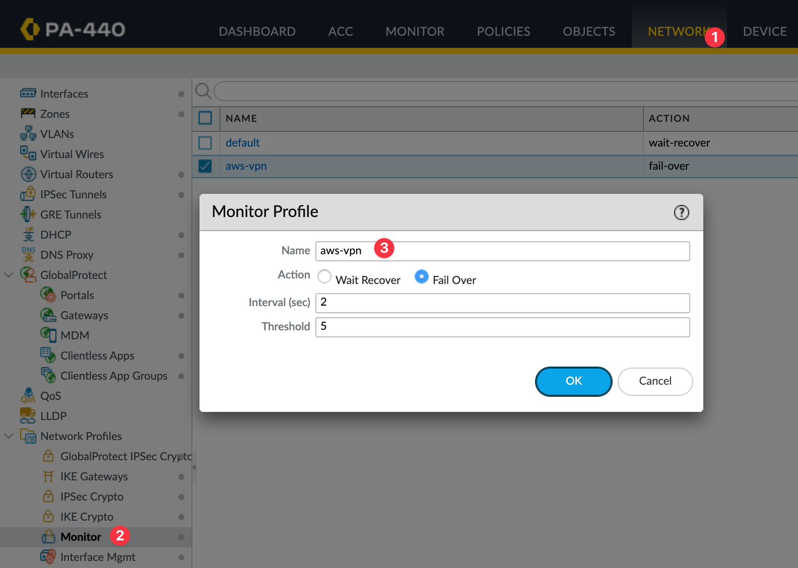
Static routing alone doesn’t support automatic failover between tunnels. If one tunnel goes down, traffic won’t switch over unless you configure it explicitly. To manage this, we use a tunnel monitor profile in the Palo Alto firewall. This profile continuously pings the AWS tunnel endpoint and checks for reachability.
If the ping fails, the firewall will remove the policy-based forwarding route tied to that tunnel, allowing the next route to take over. You can control how quickly this happens using the interval and threshold values. For example, setting an interval of 2 seconds and a threshold of 5 means the tunnel will fail over after 10 seconds of missed responses.
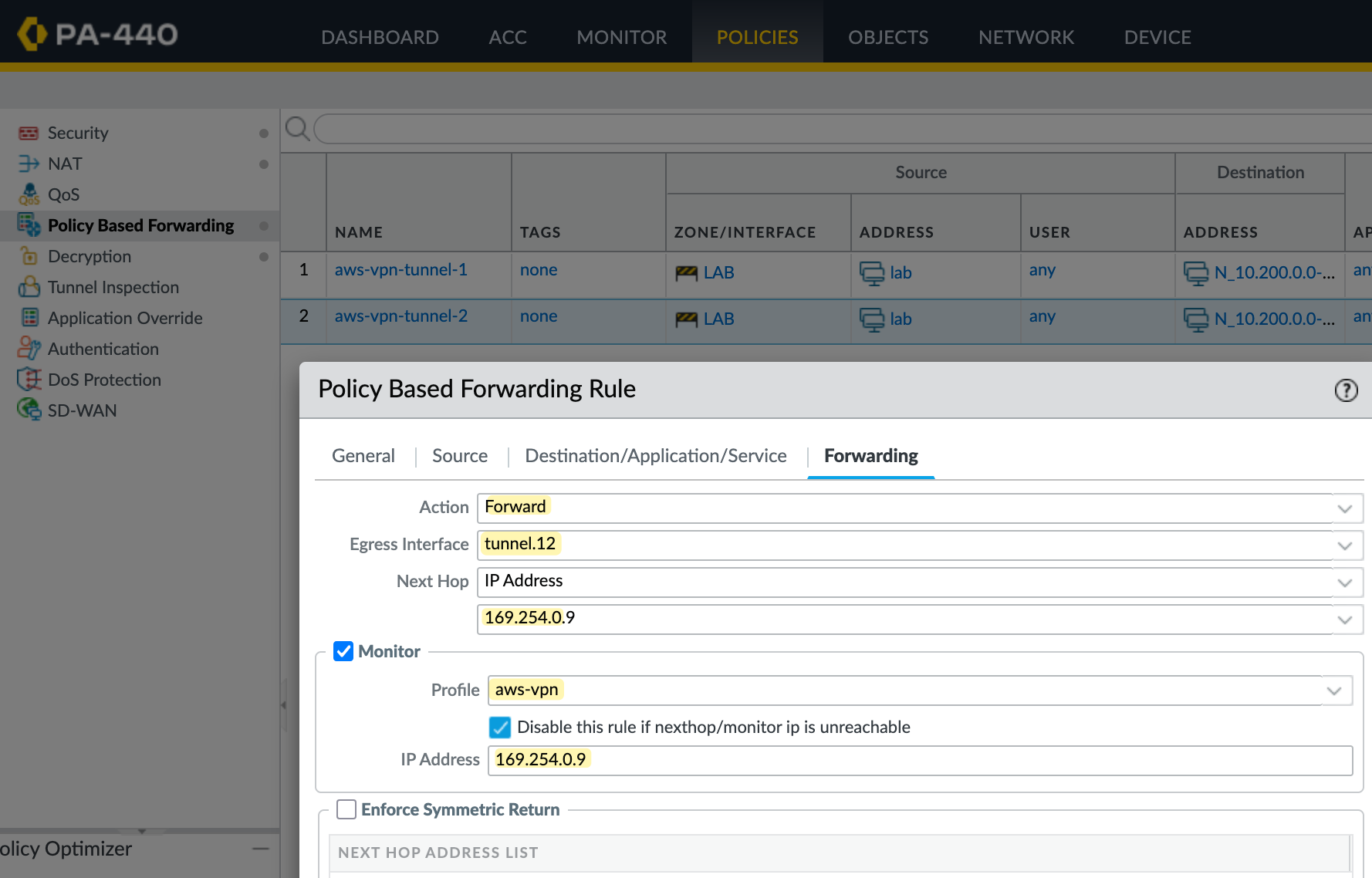
Here I'm creating two PBF rules, one for each tunnel. The source is your on-prem subnet, and the destination is the AWS VPC CIDR. If the traffic matches both source and destination, the firewall triggers the PBF rule and takes the action Forward.

In the first rule, traffic is forwarded out of tunnel.11 with the next hop set to AWS's tunnel IP. The firewall also monitors this IP, and if the ping fails based on the monitor profile, the rule is disabled. When that happens, the next packet matching the same source and destination will hit the second PBF rule, which forwards traffic through tunnel.12.
Testing and Verification
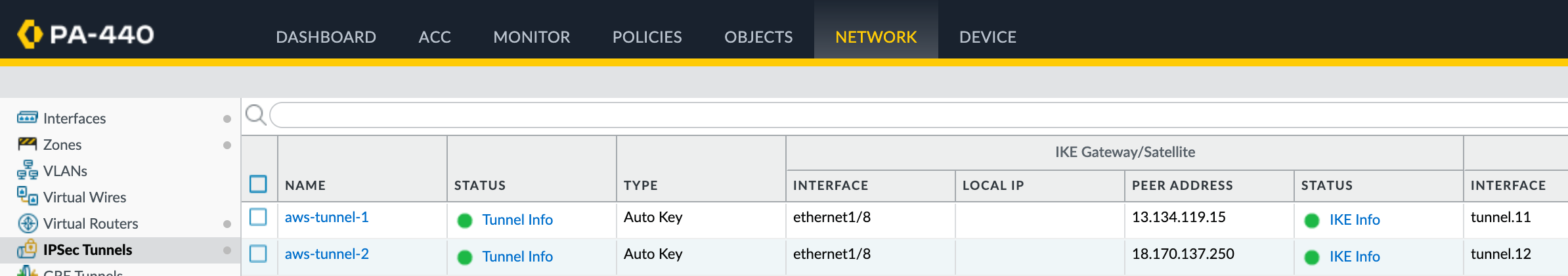
Once you configure all of this, the tunnel status on both the AWS side and the Palo Alto side should show as up.
❯ ping 10.200.10.187
PING 10.200.10.187 (10.200.10.187): 56 data bytes
64 bytes from 10.200.10.187: icmp_seq=0 ttl=126 time=14.669 ms
64 bytes from 10.200.10.187: icmp_seq=1 ttl=126 time=14.247 ms
64 bytes from 10.200.10.187: icmp_seq=2 ttl=126 time=16.423 ms
^C
--- 10.200.10.187 ping statistics ---
3 packets transmitted, 3 packets received, 0.0% packet loss
round-trip min/avg/max/stddev = 14.247/15.113/16.423/0.942 ms
That completes setting up the VPN using static routing. In the next section, we'll look at how to set it up using BGP.
Creating the VPN Connection (BGP)
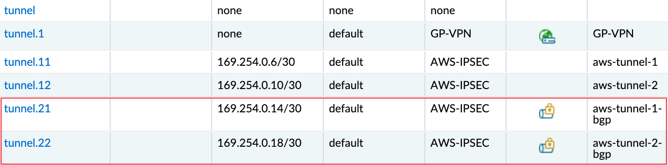
Now that we've covered static routing, let's look at using BGP with AWS VPN. I'm going to delete the existing VPN connection we created earlier and re-create it with BGP enabled. On the Palo Alto side, I'll just disable the PBF policies we created before; everything else remains the same. I'm also creating two new tunnel interfaces tunnel.21 and tunnel.22. For these, I'm using 169.254.0.12/30 and 169.254.0.16/30 for the tunnel IPs.
Of course, the public IP addresses on the AWS side will also change when you recreate the VPN. So, make sure to update your IKE Gateways on the Palo Alto firewall with the new peer IPs and the new pre-shared keys provided by AWS.
Creating the Tunnel Interfaces
As I mentioned earlier, most of the config stays the same. So let's start by creating the new tunnel interfaces. Here I've created tunnel.21 and tunnel.22 with IPs 169.254.0.14/30 and 169.254.0.18/30. These are assigned to the same AWS-IPSEC zone and will be used for the BGP-based VPN.
Enable BGP
First, let’s enable BGP. You’ll find the routing configuration under Network > Virtual Routers. Select your virtual router, in my case, it’s called default.
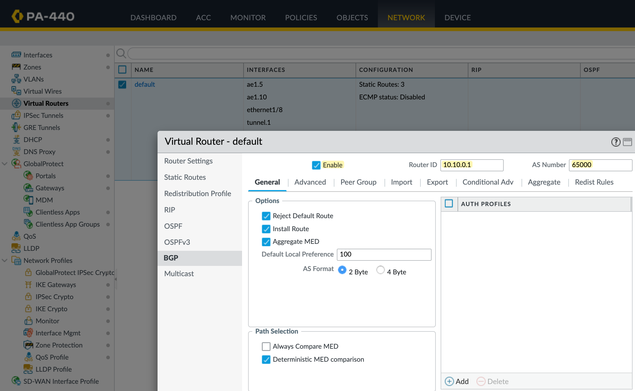
Go to the BGP tab and enable it. Set the AS Number to 65000 (this should match the ASN used when we created the customer gateway in AWS) and assign a router ID. You can leave most of the other settings at their default values.
Redistribution Profile
Next, let's create a redistribution profile. The on-prem subnet 10.10.0.0/24 is a connected route on interface ae1.10, so we’ll redistribute this connected route into BGP. If you have multiple prefixes to advertise, you can adjust them accordingly. You can also redistribute routes learned through static routing or other protocols like OSPF if needed.
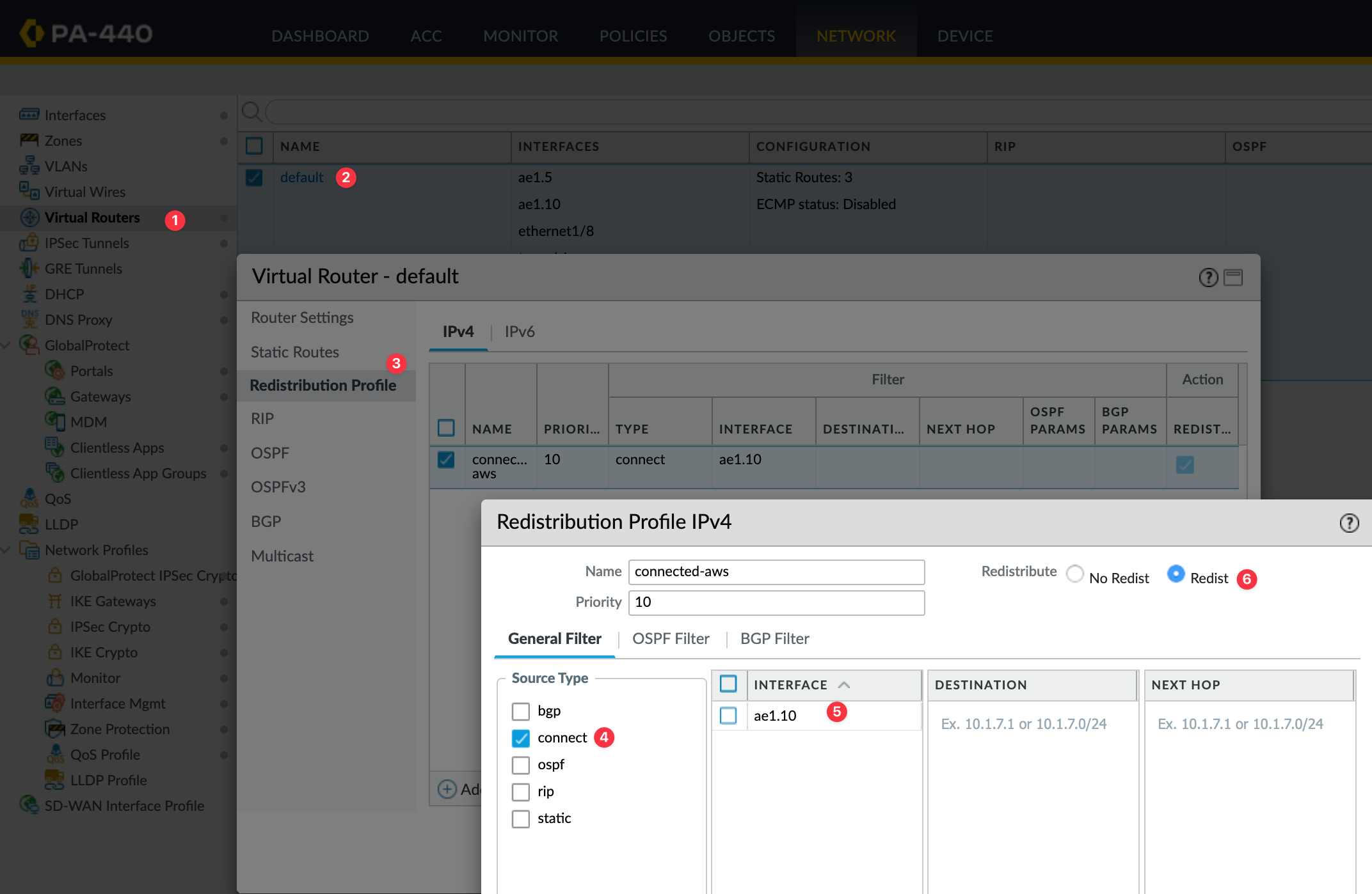
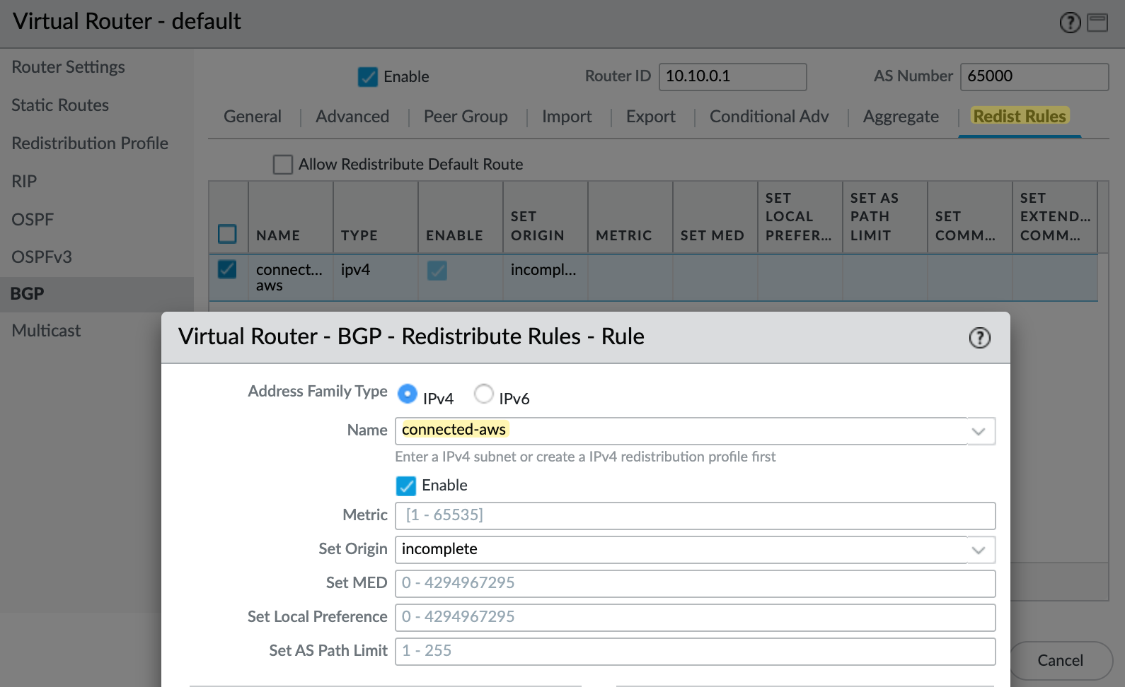
Once you've created the redistribution profile, the next step is to add it under the BGP redistribution rules. Go to the Redist Rules tab inside the BGP settings of your virtual router, and create a new rule. Select the profile you created, in this case, connected-aws and set the address family to IPv4, and make sure the rule is enabled. You can leave the rest of the fields at their default values unless you have a specific requirement.
BGP Peers
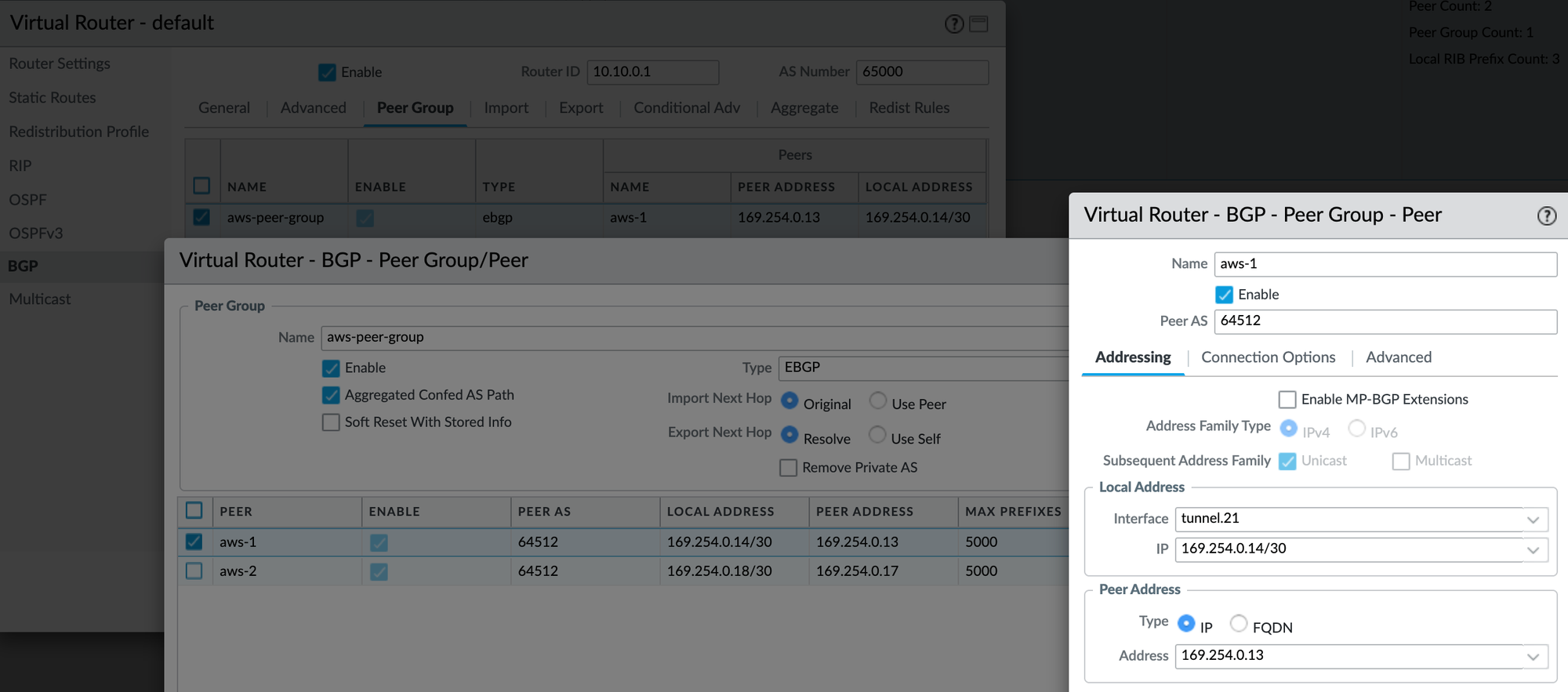
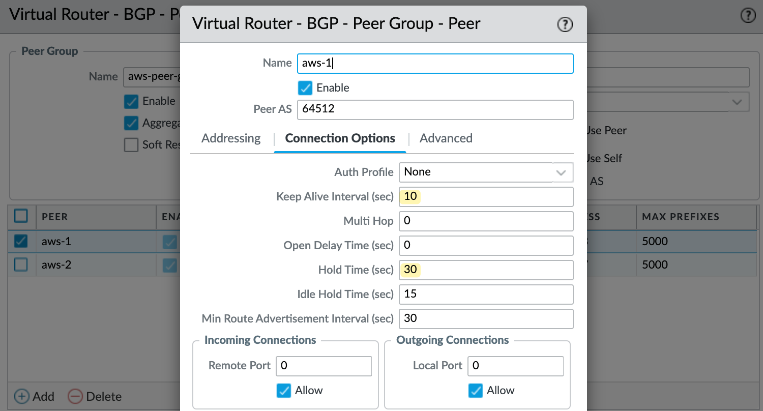
Finally, create a BGP peer group and add the two peers. For each peer, set the AWS tunnel IP as the peer address and use AWS's ASN, which is 64512. Set the local address to match your tunnel interface IP. I also configured the keep alive interval to 10 seconds and hold time to 30 seconds, as recommended by AWS.
Testing and Verification
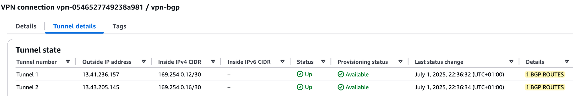
That should be it. Commit your changes, and if you check on the AWS side, both tunnels should come up. You should also see '1 BGP routes' listed, which means AWS is receiving one BGP route as expected.
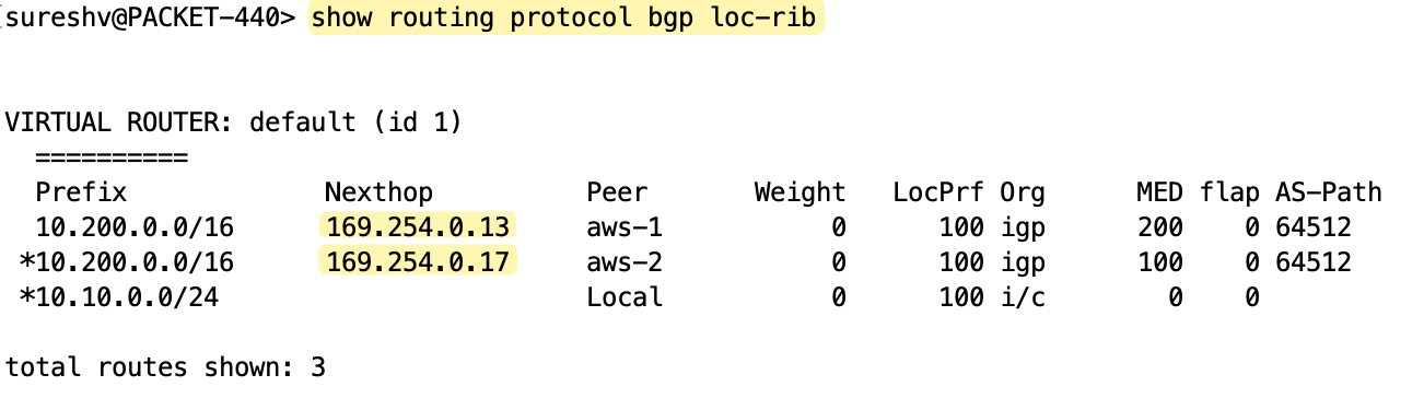
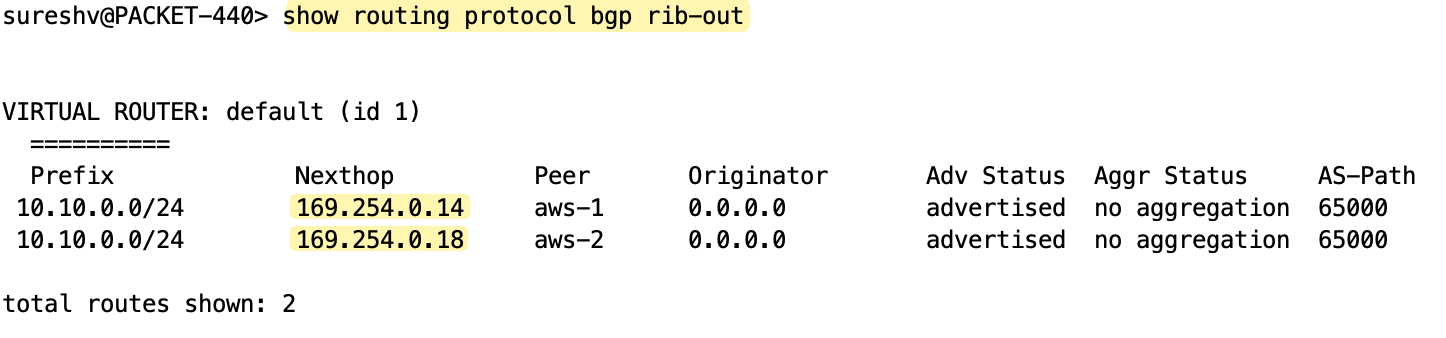
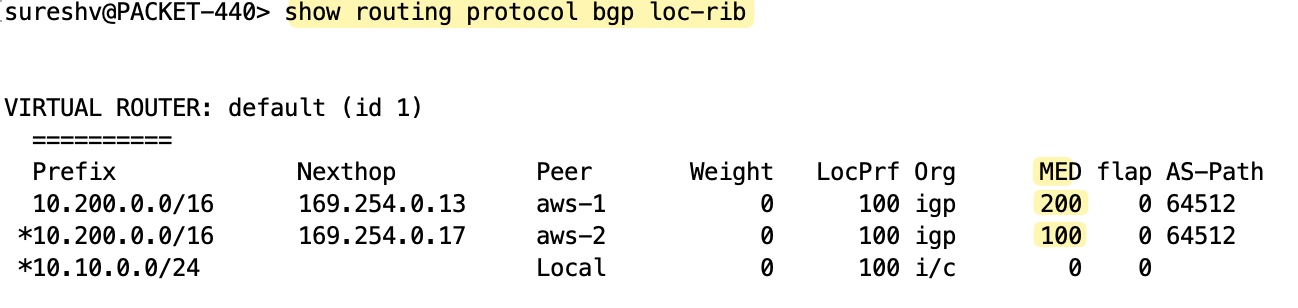
You can verify the BGP peer status and check received and advertised routes on the Palo Alto firewall using the following commands.
BGP Attributes and Path Selection
If you look at the received routes from AWS, you’ll notice that the second tunnel has a MED value of 100 and the first tunnel has 200. So, for outbound traffic, the firewall prefers the second tunnel (tunnel.22) with the lowest metric.
Inbound traffic is decided on the AWS side. For inbound traffic (traffic leaving AWS), AWS determines which tunnel to use based on BGP path attributes. If everything is equal, like local preference, AS path, MED, etc, which is the case here since we didn’t customize any of these, AWS will most likely prefer the tunnel with the oldest active route.
If you want full control over both inbound and outbound paths, you can use local preference to control outbound traffic and AS_PATH prepending to influence inbound traffic. However, AWS strongly recommends using customer gateway devices that support asymmetric routing.
For devices that support asymmetric routing, AWS does not recommend using AS_PATH prepending. This ensures both tunnels have equal AS_PATH, and the MED value set by AWS can be used to decide tunnel preference. Since both tunnel interfaces are part of the same zone in the Palo Alto firewall, the firewall allows traffic to go out through one tunnel and return through another. So we don’t need to make any additional changes to handle asymmetric routing in this case.
For devices that do not support asymmetric routing, you can use AS_PATH prepending and local preference to influence paths.
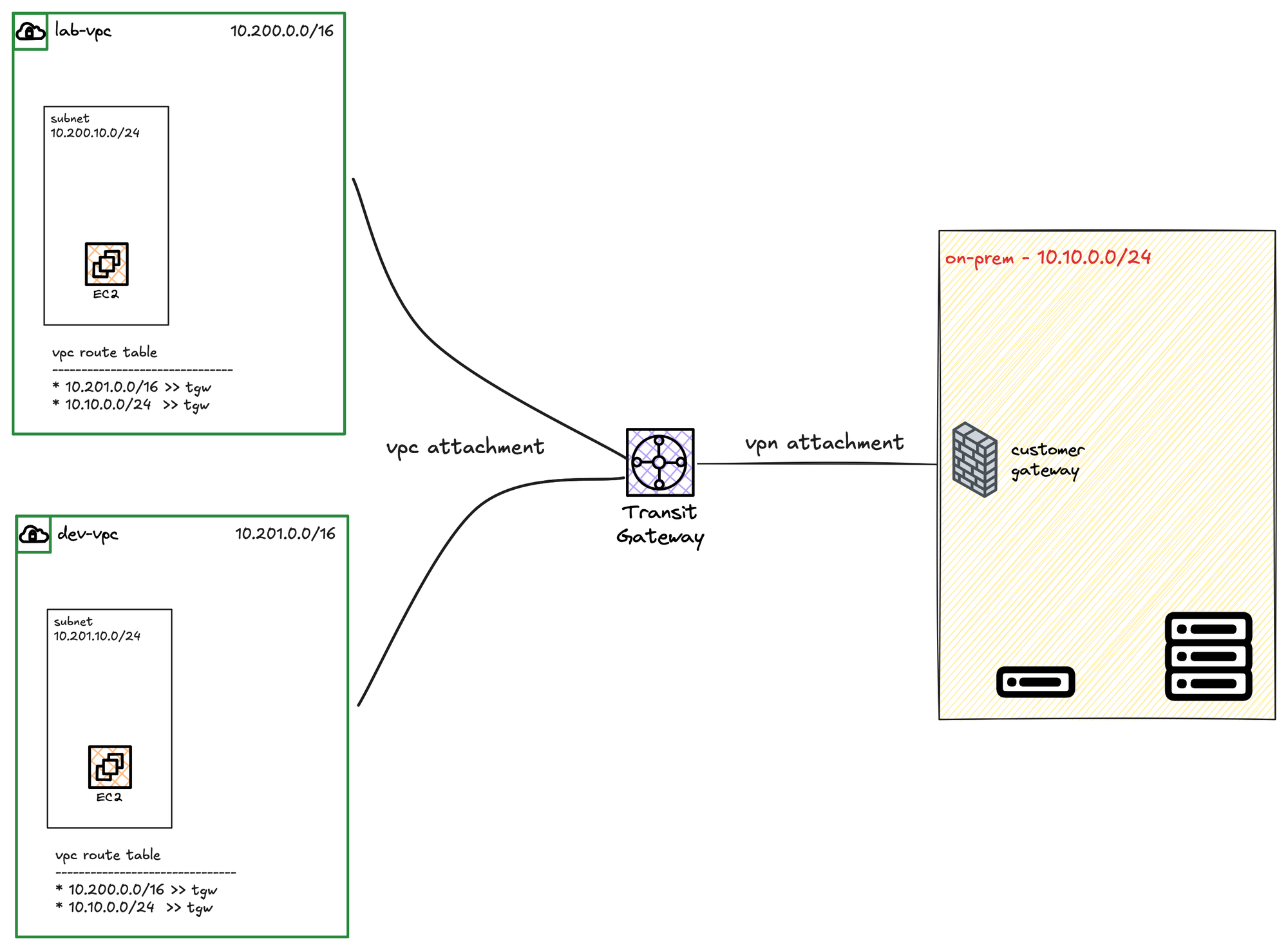
Transit Gateway AWS Site-to-Site VPN Attachment
So far, we have seen how to create a Site-to-Site VPN and attach it to a Virtual Private Gateway (VGW), but in this section, we will look at creating a VPN and attaching it to our Transit Gateway.
I assume you are somewhat familiar with AWS Transit Gateway (TGW), and here we have a TGW with two VPC attachments.
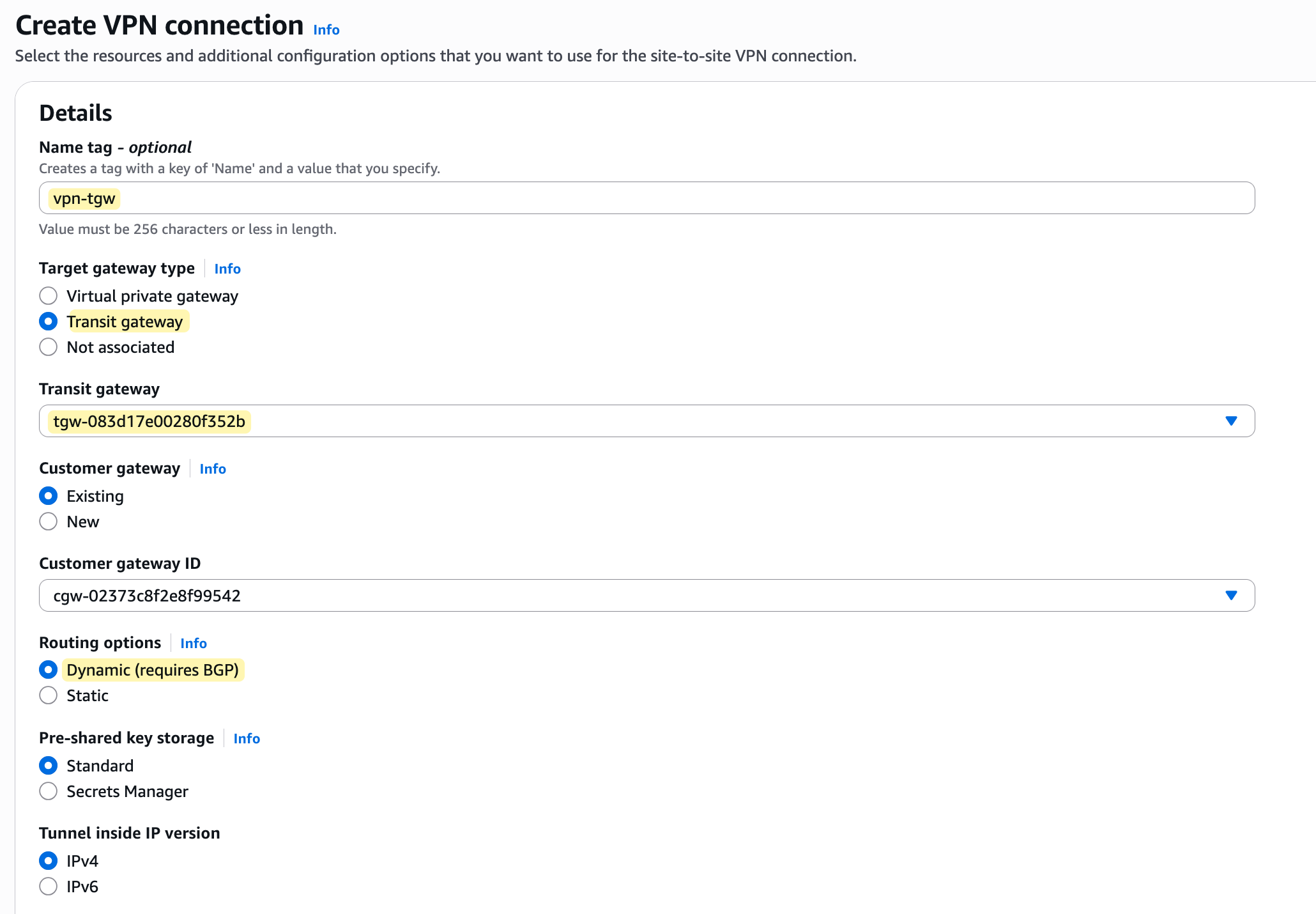
The process is very similar to creating a VPN with VGW. The only real difference is that when you create the VPN connection, instead of choosing 'Virtual private gateway' as the target, you must choose 'Transit gateway' and then select your TGW from the list. From there, everything else in the VPN creation wizard is the same.
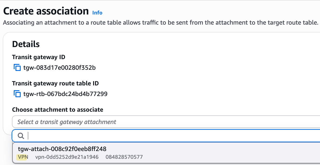
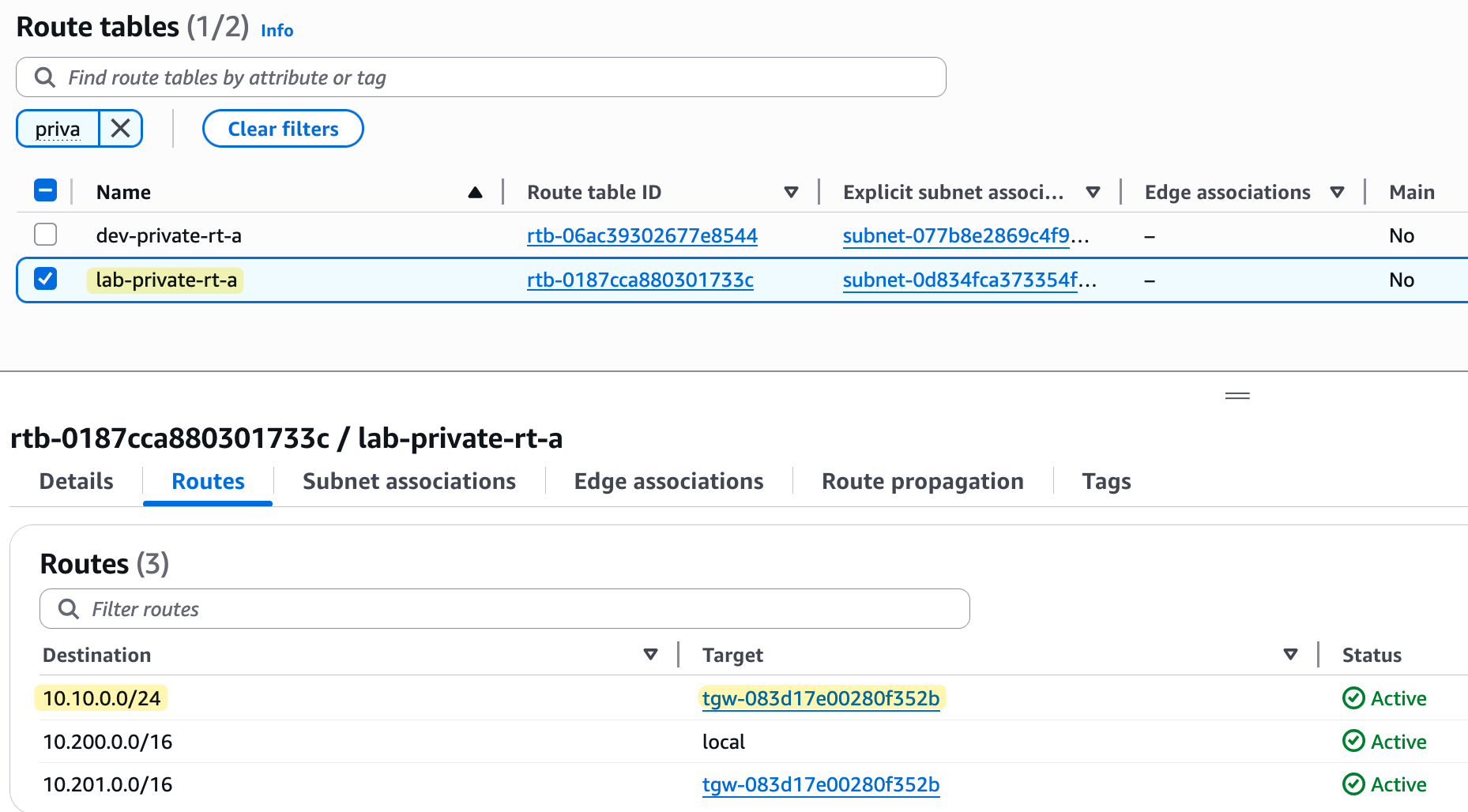
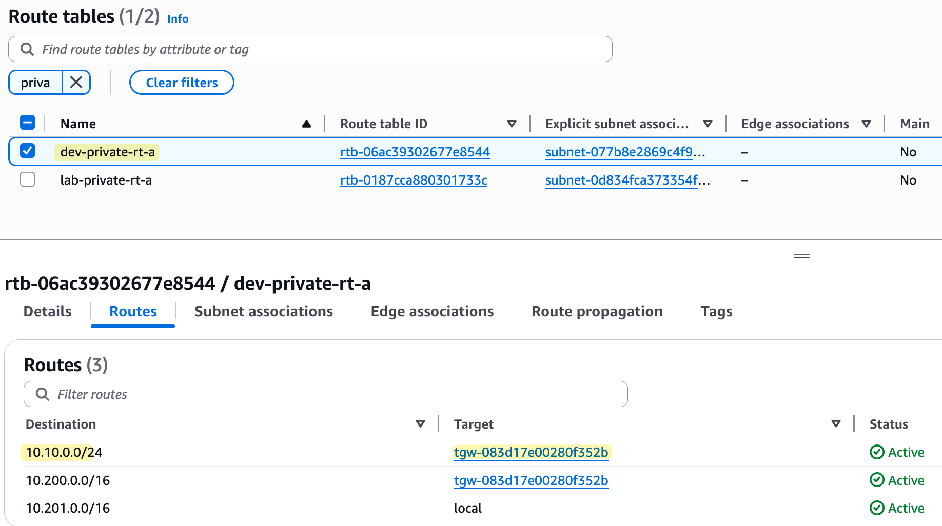
Once the VPN connection is created, you need to go to the TGW route table of your choice, create a new association for the VPN attachment, and then create a propagation for it so the TGW can learn the routes from your on-premise network.
Finally, you also need to remember to go back to the subnet route tables inside your VPCs and add a route for your on-premise network, pointing to the Transit Gateway as the target.
On the Palo Alto firewall side, the configuration remains mostly the same. The only things that change are the public IP addresses of the AWS tunnel endpoints, since we created a new VPN connection, and potentially the BGP ASN if you were to use a different one to TGW.
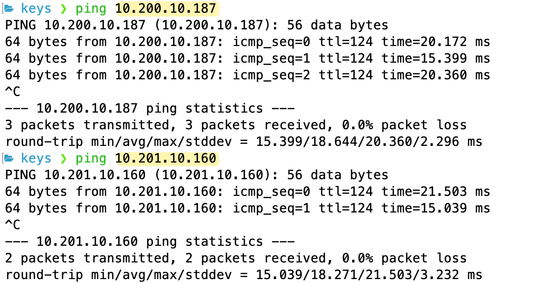
As you can see from the screenshots, our VPC route tables now have routes to the other VPC and to the on-premise network, all pointing to the TGW. Because all our attachments (the two VPCs and the VPN) are now associated with and propagating to the same TGW route table, they can all communicate with each other. Here is the ping test from on-prem (10.10.0.x) to both VPCs.
AWS TGW VPN ECMP Support
When you create a VPN connection with a Transit Gateway, it also supports ECMP (Equal-Cost Multi-Path), which is not available when using a Virtual Private Gateway (VGW). With ECMP enabled on both the TGW and your on-premise device, BGP can install multiple, equal-cost paths into the forwarding table. This allows your traffic to actively use and load-balance traffic across both of the VPN tunnels.
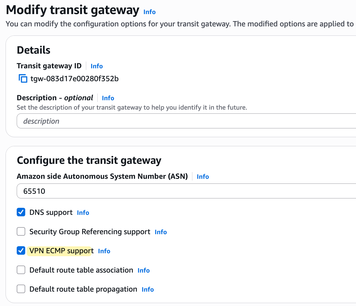
Normally, BGP selects only one 'best' path for each destination prefix and installs only that route into the forwarding table. When BGP ECMP is enabled, however, the device can select multiple equal-cost BGP paths to reach a destination, and all these paths are installed in the forwarding table for use. You can enable this feature by simply ticking the 'VPN ECMP support' box when creating or modifying your Transit Gateway.
We also have to enable ECMP on the Customer Gateway device, Palo Alto, in this case, of course.
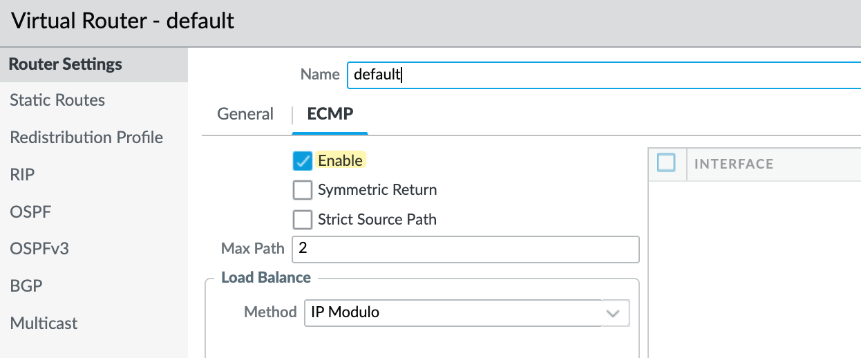
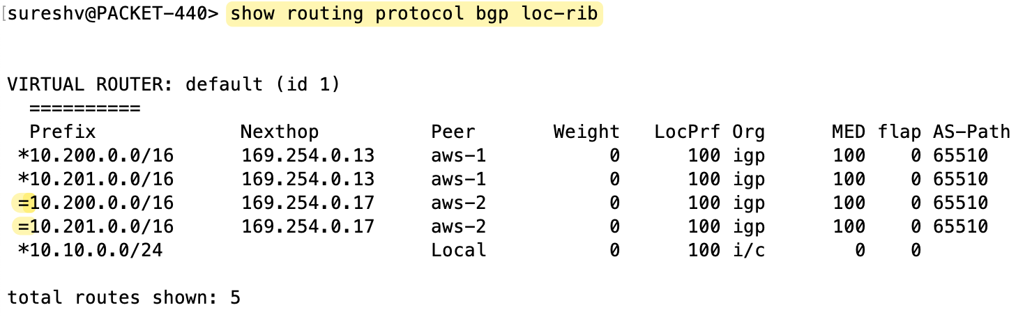
If I go and look at the firewall, I can see that for the routes to my AWS VPCs, both paths via the two different tunnel interfaces are installed and active in the forwarding table.
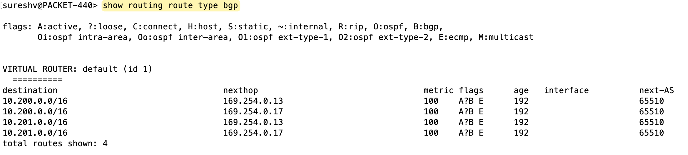
If we were to have the VPN terminate on a Virtual Private Gateway (VGW) instead, we wouldn't see this behaviour. With a VGW, you would only see one active route in your firewall's forwarding table.
AWS ECMP - A Few Considerations
By enabling ECMP (Equal-Cost Multi-Path), we can load balance traffic across both VPN tunnels. But keep in mind, a single flow will only ever use one tunnel. AWS uses a hash based on the protocol, source IP, destination IP, source port, and destination port to determine the tunnel. So once the flow matches the hash, it sticks to that tunnel.
I also noticed something interesting when using VPN with TGW. Regardless of whether ECMP is enabled or not, AWS sets the MED value to 100 for all prefixes. This is different from how it works with VGW, where the tunnels had MED values of 100 and 200.
Now, if ECMP is disabled on both the TGW and the customer gateway, AWS says that traffic from AWS to the on-premises network is sent over the "preferred" tunnel, which is randomly chosen by AWS. I find the word "random" a bit vague here. I haven’t found any solid explanation on whether AWS follows BGP path attributes when selecting the tunnel. For example, if everything else is equal, AS path, local preference, and MED, will AWS choose the oldest path? It’s unclear from the docs.
Anyway, if you plan to use ECMP, make sure you don’t modify any BGP path attributes. For ECMP to actually work, the AS path, local preference, and MED values must match. If you don’t want ECMP, then disable it on both the TGW and customer gateway. In that case, you can control traffic flow using local preference, MED or AS path prepending.